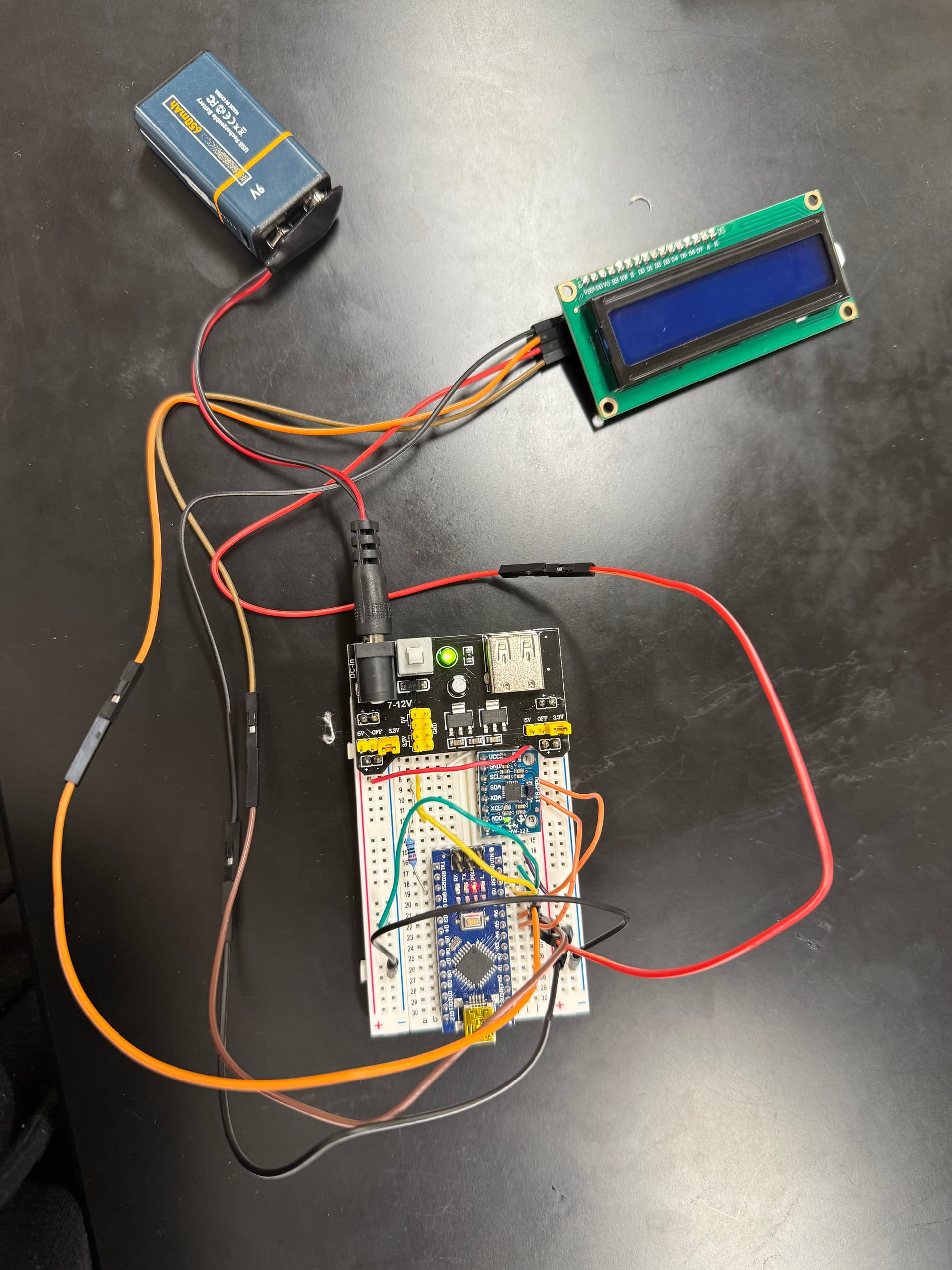
We are attempting to power our Arduino project with a 9V battery, and it seems to be insufficient. We don't believe that its the wiring because it works fine when plugged into the computer. This would have to power an Arduino nano, an MPU-6050 accelerometer/gyroscope and an LCD I2C display. I've included a picture below. The lights for the Arduino pieces light up as if it turns on but the LCD doesn't light up and the code doesn't run. Any ideas? The thought is just that we need a bigger battery.
Welcome to the forum
That is very likely as that type of battery cannot supply the current required to run most Arduino projects for more than a few minutes
Can you measure the battery voltage while it is under load ?
You appear to be trying to run a 5V Nano off of 3.3V applied to Vin. I can't be sure where that purple wire is going, but it appears to be connecting the 3.3V rail to Vin.

Vin requires a minimum of about 7V to regulate down to 5V for the Nano. Even if that is a 3.3V Nano (which would be something new to me), you're still not going to get away with putting 3.3V in Vin.
I can't tell from that mess of wiring what you're powering the LCD with, but unless that display has been modified to run at 3.3V (or it's a real 3.3V display), you are unlikely to be able to adjust the contrast sufficiently to be able to see anything.
1 Like
We have this switched to the 5V pin on the battery adapter and it works/code runs however the LCD is dim and the print on the screen is hard to read is that an amp issue too or is that code. The code that I have doesn't necessarily control the brightness at the moment.
I don't have a voltmeter on hand but we switched the battery adapter to the 5V setting. We had it on the 3.3V setting by accident. The LCD now lights up and run code but its dimly lit and the words are barely visible. Is that also an amp issue/dying battery problem or a need for a bigger battery. Someone also mentioned possibly adjusting the brightness with the code which I haven't thought of yet.
This is the code
//code reads the z-axis data and displays it on the LCD screen

#include <Wire.h>    //Include wire library for communication between Arduino and MPU6050/LCD
#include <MPU6050_light.h>  //Include library for MPU communication (motion-tracking device)
#include <LiquidCrystal_I2C.h>  //Library for communication w/ LCD Display using I2C

MPU6050 mpu(Wire);   //Create object mpu
LiquidCrystal_I2C lcd(0x27, 16, 2);     //Define LCD address and dimension (screen size 16 columns and 2 rows)

unsigned long timer = 0;  //refresh rate of the LCD screen (no delay)
float KneeAngle=180-(int)(mpu.getAngleZ());
float Angle=(int)(mpu.getAngleZ());
float RPM;
bool CompleteRev=false;
unsigned long start;
unsigned long RevTime;


void setup() {

  Serial.begin(9600);    //Start serial communication (rate 9600)
  lcd.begin(16,2);     //Start LCD Display
  lcd.backlight();   //turn on LCD backlight
  Wire.begin();  //start I2C communication
  mpu.begin();    //Start MPU6050 sensor

  lcd.setCursor(0,0);//set cursor to first column first row
  lcd.print("Frankenstein");
 delay(5000); //delay 5 s

 lcd.setCursor(0,0);
  Serial.print(F("MPU6050 status: ")); //print that
  Serial.println(F("Calculating offsets, do not move MPU6050"));   //new line print that
  lcd.print("Remain Still");
  delay(5000); //wait 5s before moving on
  //these three lines print on the Arduino but won't be seen by the patient

  mpu.calcGyroOffsets();     //Calibrate gyroscope and compensate for offsets
  Serial.println("Done!\n");
 lcd.print("Ready");//waits for calibration then prints ready on the LCD
}
void loop() {
  mpu.update();    //Get values from MPU and update accordingly

  if ((millis() - timer) > 100) { // (check if 100 ms has passed)
    timer = millis(); //reset time to current time
    lcd.clear(); //clear LCD of old data
    lcd.setCursor(0,0);
    lcd.print("Angle: ");
    lcd.print(KneeAngle); //Print Z angle value on LCD
    Serial.print(KneeAngle);//same on the serial monitor
    delay(10); //delay to avoid flickering
  }
  //rpm
   if (Angle >= 0.0 && Angle <= 360.0 && !CompleteRev){
    CompleteRev=true;
    start=millis();
  }
  if (Angle == 0.0 && CompleteRev){
 RevTime=millis()-start;
 RPM=60000/RevTime;
 delay(50);
  }
 Serial.print("RPM=");
 Serial.print(RPM);
 lcd.setCursor(0,1);
 lcd.print("RPM=");
 lcd.print(RPM);
 delay(10); //flicker
 CompleteRev=false;
  }
Why is a 9 V battery more appealing than using 6 x 1.5 V, or two 3.7 Li batteries?
If you want to use a 9V battery that would work but you would have to parallel a dozen maybe more and it will run for a while.

That is in series, now show parallel:-)
1 Like
Desperately trying to get hold of the guy on Youtube ![]()
Ideally we would use a single battery for compactness. We need this to fit on the side of a knee brace essentially (batteries and hardware) so many batteries in parallel wouldn't be efficient for this project for the reason that the batteries will take up too much space.
We only need this to run for 45 min at a time. The 9V battery is rechargeable so the idea was after each 45 min use it would be fully recharged.
Where will the display go?
1 Like
It's probably time to conclude that the idea was not a very good one, don't you think??
1 Like
This topic was automatically closed 180 days after the last reply. New replies are no longer allowed.