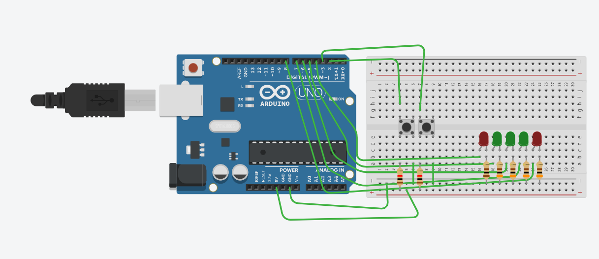
Hi, I'm trying to control the speed of some LEDs using two buttons (one to increase and one to decrease) using interrupts but it only triggers the function once.
how did you wire the buttons in real life and not on the model? best would be to connect in diagonal across the button to avoid connecting to 2 pins that are "the same".
using the builtin pull-ups would make it easier (just invert the logic)
(and we usually place the current limiting resistor on the Anode of the LED)
speed could be modified by the ISR whilst the function is being called... a non blocking approach would be better or make a copy of the speed in a critical section and use the copy and only take into account changes at the next iteration.
OK - may be I generalised abusively with "we" and it might be just my experience.
I understand that placing the resistor on the anode side or the cathode side has no impact on the LED’s performance or protection because the resistor’s primary function is to limit current, which is determined by Ohm’s / Kirchhoff’s Laws and the resistor’s position in the circuit doesn’t affect this calculation.
it's just that withthis placement the components are in an easy to interpret order (may be for me, I'm a software guy) with the resistor limiting current "before" it reaches the LED. Feels more natural to me and easier to follow the circuit.
Yes, I'm using UNO R3,
LEDs light up in both real life and in the simulator
It just the speed that's not working (changing) in real life.
In the serial monitor speed changes just once (+-20) and then no matter how many times I press the button it doesn't work
I'll follow the suggestion mentioned above and come back
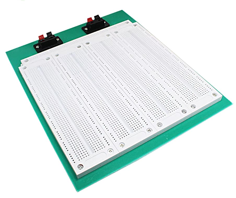
I was using this breadboard and here all the vertical lines are not connected. It's connected in block of 3. So my common ground wire was working for the leds but not for the buttons as they were further away. @J-M-L suggestion of using builtin pull-up also made the circuit simpler.
Btw how many pullup-resistors I can use on arduino uno?
What is more natural to experienced engineers (because it's rooted in history) is to connect the LED's anode to VCC (resistor on either side) and the cathode to the I/O pin. This harkens back to the days when logic circuits could sink more current than they could source. So, it was safer to sink current in order to turn ON the LED.
There are no vertical lines on that breadboard, it is at about 45 degrees angle to the camera. So there are are only SE-NW and SW-NE lines. Please explain what you mean.
What is connected in block of what 3 items? Again, please explain what you mean.
I can see exactly what is connected to what on your breadboard simply by looking at it. But I am familiar with breadboards. I want to check that you truly have understood what is connected on your breadboard, to avoid more problems in future