I've got some code to put the Nano IOT 33 into deep sleep and wake up when a button is pressed but it doesn't seem to be working. The code is
/* Test Deepsleep wakeup

#include <ArduinoLowPower.h>


void setup() {
  // put your setup code here, to run once:
  Serial.begin(9600);
  delay(1000);
  Serial.println("before LED");
  pinMode(LED_BUILTIN, HIGH);
  pinMode(4,INPUT);
  Serial.println("going to deep sleep in 5!");
  delay(5000);
  LowPower.attachInterruptWakeup(4,loop, CHANGE);
  LowPower.deepSleep();
}

void loop() {
  // put your main code here, to run repeatedly:
  Serial.println("Woken up!!!");
  while(1);
}
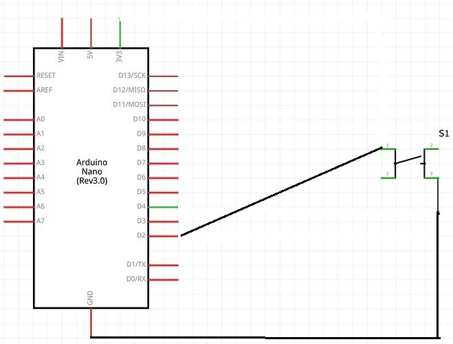
I've connected the 3.3V rail via a push to make button onto pin 4 which i thought would generate the interrupt. Could someone point me in the direction of why it's not working? I've tested the button using a LED so that's working. The LED doesn't light up either.
fisrt: please tell me you use your sketch without the /* */ before and after: if your code is grey, it is "commented" and not compiled. In this state, you actually send a blank test to your board.
Remove the /* and */ and compile again.
second: can you join a schematic of your drawning? Typically, you can't ask your board to power up the output in 3,3V during sleep, so your button is not powered up, and can't send any current to your pin.
You have to wire your button to your board, but from an external source of current. You may google for such a circuitry (sometimes including a mofset or transistor, external to your board).
I'm beginning to see that it needs some other power to wake it up. What I'm trying to do is have a button that puts it to sleep and another that wakes it up.
the wiring will be good to put the board into sleep.
But then, your button won't be powered up, so you can click on it as strong as you want without any results!
So your "wake-up button" has to be powered another way (not by the card itself). That way, it could be able to send a current to a pin that could trigger the wake up.
I hope it is clear for the theory. Sorry I am not good in electronics, so I propose you search here in this forum, or with google, a good example of circuit that operates the way you want.
This post caught my attention as I asked myself this same question recently because of a project where I use a PIR sensor to wake up an ESP32 CAM. I´ve found out that the ESP´s 3V3 rail keeps energized even while the board is sleeping.
I also have a Nano 33 IoT, so I decided to do some testing for future reference of others who find this post. After some experimenting, I´ve found out that:
The 3.3V port of the Nano 33 IoT was also still alive during sleeping (measured with a DMM);
I don´t know how to explain it, but in my Nano, PIN 4 didn´t work to wake up the board. I used PIN 2 instead.
I wouldn´t connect things as you did, because while the button is not pressed, the pin signal can assume any value (fluctuation). If you want to wake up the board by providing 3V3 to the pin, you should add a pull-down resistor to your circuit and make sure the pin reads zero while the button is not pressed.
But a better way to do it is setting the pin as INPUT_PULLUP and connecting your button from it to GND. So the pin will have the state HIGH until the button changes it to zero. No resistors needed.
You can test the code below. It will turn off the LED-BUILTIN after your 5 seconds delay. Then it will turn on the led when the button is pressed (connected to PIN 2 and GND).
The '3.3V Port' of most all Arduino type boards is not a port that it output from the actual microcontroller, its the incoming voltage supply to the microcontroller from a voltage regulator.
So if the '3.3V Port' were off the microcontroller would also be powered off and not just asleep.
This works thanks everyone. I'm sure I have to turn on some items when woken up as a message using Serial,println does not appear after the board has woken up again.