I'm trying to test my board pins, because of some I2C errors I've been having, and I think I found a potential cause :
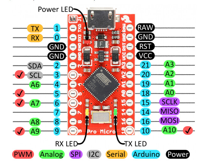
I'm using an Arduino Pro Micro 3.3v, and I'm testing pin 2 and 3, the one for using the I2C.
Pin 2 seems to be working, it display seemingly correct results.
Pin 3, on the other hand, seems to be bugged : it doesn't seem to send anything, because the analogRead of Pin 9 doesn't change in correlation with whether it's connected to it or not. Could I have found the issue ? Or is it just something simple that I'm missing ?
I see the prob! you're connecting pin 6 to pin E! LOL
Have you tested all the other pins, is this the only one? If yes, is there anythingbelse wired in? If no, sounds like a fail. Got another unit yo test with? Does it behave same or different?
I was thinking that a resistor and led between pin and GND could test one IO at a time while the code blinked them all. Set the GND end and move the other, resistor end from pin to pin watching for blinks. If you would do them all at once, get resistors that limit the total to 200mA, max source/sink current for most AVR-duinos (MCU chip limit) so 1K - 2.2K resistor makes a nice indicator led.
You could just stick a jumper in the pinhole and
set OUTPUT LOW and wait 1 milli
set INPUT
read the pin and print it
set OUTPUT HIGH and wait 1 milli
set INPUT
read the pin and print it
If you fill the wire with charge and make the pin INPUT, it does not ground the wire. When an INPUT is not being read it is electrically neutral, called the Z-state as opposed to OFF, ON, and PULLUP states, electrically Zero.
The OUTPUT HIGH 5V charge mainly stays in the wire. AVR docs tell that each digitalRead() eats 1 microAmp of charge. Count the number of reads it takes in a fast loop before the charge drops below 1.1V and reads LOW. In the presence of oscillating field(s) it may never read low, you can detect EM noise and learn about unterminated inputs!
Yup, tested all other ones, they all respond normally, exept for Pin 3... Could it be that because it's the SCL pin it behave differently ? Or is it just ded ?
I tried it with Pin 2, 3 and 4 but without a resistor, and it works on 2 and 4, but not 3.
What would the resistor accomplish there ? I'm not very good with electronic just yet, would it make a difference ?
The resistor would slow the current from the pin through the led if you have the led turmed the right way so it lights the led without oversupplying current which damages the pin and the led and can kill either quickly.
On an Uno R3 you can replace the chip with a bootloaded chip that you can learn to do to new blank chips that ran a bit over $2 ea in 2019. I have bigger roll-your-own Duino chips (when I make my own, haven't smoked one yet, says GFS) they have 16K RAM, 2 serial and 32 robust AVR IO pins.
Did you learn basic physics in school? It helps with electronics.
Most accelerometers are 3.3V only, but the Pro Micro is 5V.
You need a logic level converter to make that connection. Otherwise you can destroy one of both of the connected devices, and that may explain what happened in this case.