Is this circuit correct?

Is the wiring of this circuit correct?

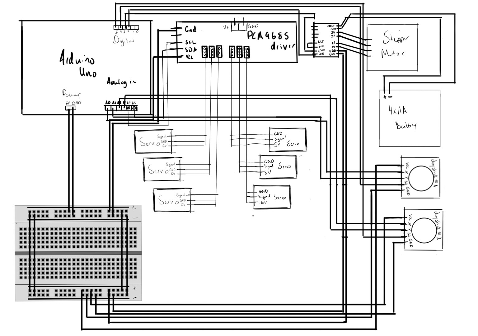
This circuit’s goal is to be put into a robotic arm (see the model here) we’ll be powering the 6 MG966R servos with a 5v 10A switching power supply which isn’t shown here (example here and the stepper motor with simple AA batteries in a housing. The Arduino will be powered by a USB cable which is not shown in the diagram. We plan to control the motors with the joystick movement.

Also, this is our first project working with an Arduino and wiring, should we include resistors or capacitors in the circuit for safety reasons? When should we include resistors and capacitors?

here's a schematic diagram, if you cant make anything out please ask me (It was a bit rushed)

Update: I think I have no way of connecting the stepper motor driver to the breadboard so ill need another breadboard

An MG966R could draw 2-2.5A stall, so a 10A supply for six servos might not work.

Which stepper motor (link), and which driver.
Popular drivers like the A4988, need a minimum supply of 8volt.
A current controled driver also needs a 100uF cap on it's motor supply pins.
Leo..

Impossible to tell from a Fritzing with meaningless parts and pin labels. Better supply a symbolic circuit diagram.

Proper placement of capacitors is Impossible with a breadboard.

1 Like

Breadboard can't handle motor currents. You need better interconnects no matter what.
Please hand draw a schematic with labels, part #'s and pins.

1 Like

You posted a petty picture but it is useless to evaluate a project. Best to post an annotated schematic (the language of electronics) and links to technical information on all the hardware devices.

Hi, @engineer44
Welcome to the forum.

For this level of project, can I suggest you begin to draw schematic diagrams.
The Fritzy images are very hard to follow.

An image of a hand drawn schematic will be fine, include ALL power supplies, component names and pin labels.

Thanks.. Tom.. :grinning: :+1: :coffee: :australia:

with all those servos won't we need something like 18A of current?

here's the link for the stepper

I looked at a video about the stepper motor driver and they recommended a 47uF cap on the supply pins, this is all very confusing.

I'm thinking of getting a 12V 4A power supply for the stepper motor, would that be enough?

Thanks!!

I drew a schematic diagram, but some labels are a bit hard to see so please ask me about any if you can't make them out

The breadboard is used to plug more than one thing into the Arduino's 5V and ground pin. What do you mean by better interconnects? Here's a schematic I drew

Breadboard and loose wires won't hold together forever. The connections will loosen as they are rotated. Additionally, the breadboard is not capable of handling the motor currents.
Look up the STALL CURRENT and multiply that by the number of motors. Then add the mA needs of each chip. Add 25% for headroom, and round up to the next Amp and use that to size your power supply.

I don't understand what you mean by each chip, I don't think we're using any since the power supply is purely for the servo

I apologize for my lack of knowledge :sweat_smile:

I've seen here that another way is simply connecting all the 5v wires together into one, would that work here too?

Update: here are some useful links since the forum wont let me add more than 2 links in the post

Servo
Stepper Motor

Joystick
Power supply for the servos (5V 10A)

Stepper driver
Servo Driver

To post images etc. you need trust level 1, you can get there by:

  • Entering at least 5 topics
  • Reading at least 30 posts
  • Spend a total of 10 minutes reading posts

Users at trust level 1 can...

  • Use all core Discourse functions; all new user restrictions are removed
  • Send PMs
  • Upload images and attachments

This topic was automatically closed 180 days after the last reply. New replies are no longer allowed.