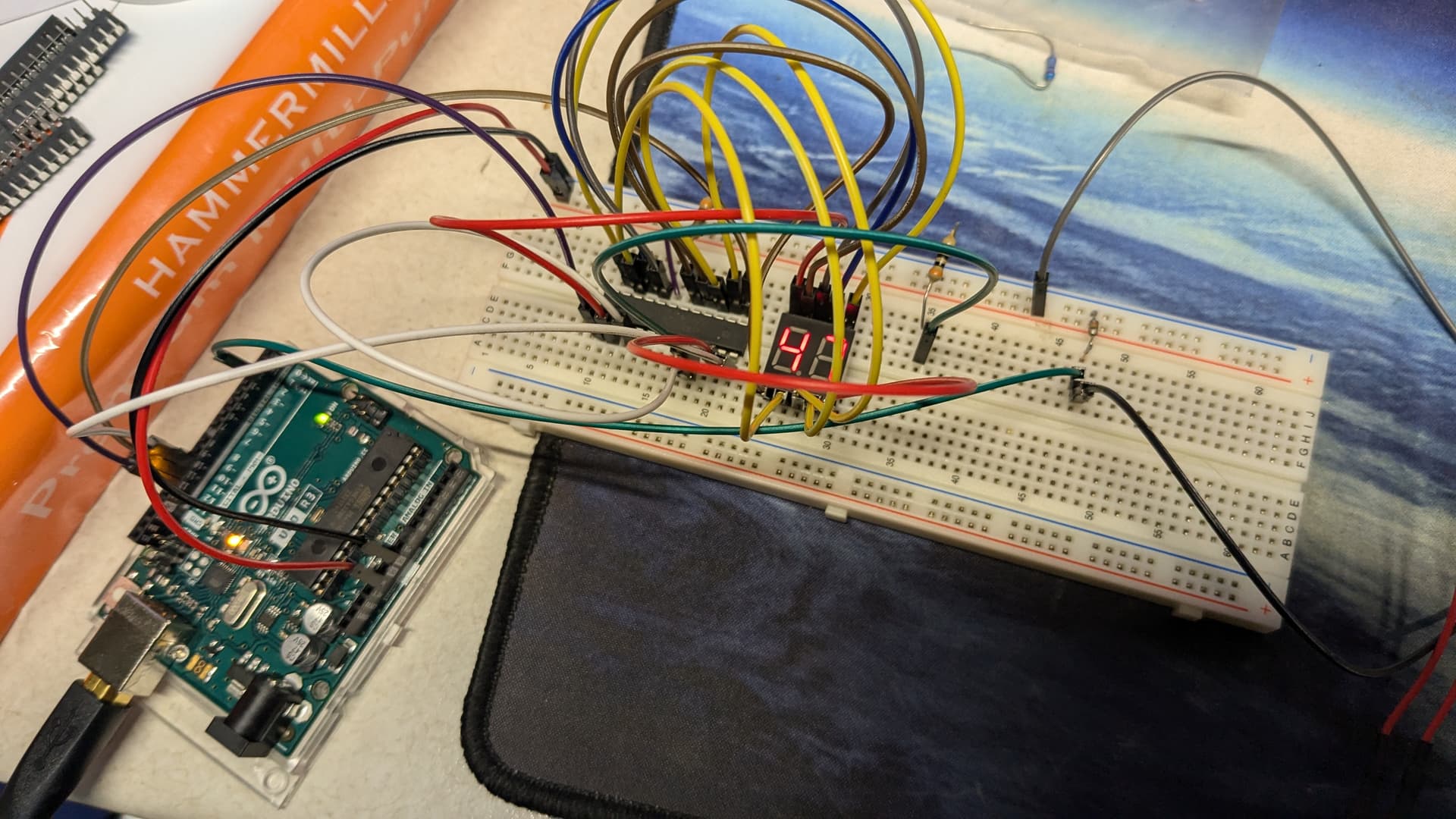
Hello all, first time arduino user here, so forgive any of my ignorance  I think this is the right category, but if not I apologize!
I've been trying to use an Uno with a MAX7219 to drive a dual-digit 7 segment display. I followed this video closely to and tried to replicate it (just with 1 button and 1 dual-digit display for now)
The 7 segment display I have is actually from the same amazon link as the video creator used, however they have changed to a slightly different part number (CL3621AH, NOT the 5621BH) which has a slightly different pinout for the segment pins. I used the code from his video and everything mostly works, the numbers start at 00 and pushing the button increases the number by 1 each time. But there is some strange behavior happening. Occasionally the display just goes completely blank, all segment turn off. This happens randomly. Sometimes when I push the button the first time, sometimes I can push it a dozen times or more, but eventually the display always goes off. I have tried a different 7219 chip thinking it may be a faulty chip, but the exact same behavior occurs. I can hit the reset button on the arduino and it will reset to 00, i start pushing the button and eventually it goes off again. I have confirmed via serial monitor that the code is still working correctly (displaying the value in the serial monitor, which keeps increasing with each button press) I decided to measure the voltage from the common cathode to the segment pins. While working, it shows -3.3v, but as soon as it turns off, it shows around -5v. I have tested the display manually using 5v (with a 10k resistor) and confirmed all segments light up properly using 5v. Im far from an expert so Im not sure why the reading is - from the 7219, but I assume thats intended. But I am confused why it measures -3.3 and works, but doesnt work with -5. Perhaps there's a very simple reason for all this that I am simply too inexperienced to understand.
This is the code im using, copied directly from the author of the video linked previously
#include "LedControl.h"  // Library used for communcation with 7 segment

LedControl lc=LedControl(12,11,10,1);  //  (DIN, CLK, LOAD, number of Max7219 chips)

// Variable to hold current scores
int displayone=0;
int displaytwo=0;

// Variables to split whole number into single digits
int rightdigit;
int leftdigit;

// Switches pin connection to Arduino UNO
#define switchone 2
#define switchtwo 3


void setup() {
  pinMode(switchone,INPUT_PULLUP);
  pinMode(switchtwo,INPUT_PULLUP);

  lc.shutdown(0,false);  // Wake up MAX7219

  lc.setIntensity(0,7);  // Set brightness to medium

  lc.clearDisplay(0);  // Clear all displays connected to MAX7219 chip #

// Put zeros on both displays at startup

  lc.setDigit(0,0,0,false);  // (Max7219 chip #, Digit, value, DP on or off)
  lc.setDigit(0,1,0,false);

  lc.setDigit(0,2,0,false);
  lc.setDigit(0,3,0,false);

}


void loop() {

  // If switch 1 is clicked
  if (!digitalRead(switchone)) {

    displayone++;  // Increase score by 1

    // convert whole number to single digits
    rightdigit=displayone%10;
    leftdigit=displayone%100/10;

    // Display extracted digits on the display
    lc.setDigit(0,0,leftdigit,false);
    lc.setDigit(0,1,rightdigit,false);


    // Wait until switch is released to continue
    while (!digitalRead(switchone)) {
    }
    delay(5);  // Small delay to debounce the switch
  }

    if (!digitalRead(switchtwo)) {

    displaytwo++;

    rightdigit=displaytwo%10;
    leftdigit=displaytwo%100/10;

    lc.setDigit(0,2,leftdigit,false);
    lc.setDigit(0,3,rightdigit,false);

    while (!digitalRead(switchtwo)) {
    }
    delay(5);
  }
}
The one thing I didnt include in my circuit is the capacitors. I asked a friend whos much better with this stuff and he said he didnt think that would cause this issue, but I realize that could be incorrect. I dont have any loose caps hanging around to throw into the circuit currently, so Ive tried without one. I will check my dead electronics pile so see if I can find the correct caps and pull them from another board. If my issue is purely the lack of caps, Im going to feel like a bigger nub than I already to 
I also used a pull-down resistor (10k) from the 2 GND pins on the 7219, because the display wont light up at all without that, which is strange because none of the other circuits ive seen using a 7219 use a pull down in this way. Other than that, my wiring is exactly the same as in the linked video, just with 1 dual-digit display and 1 button instead of 2. I would make my own diagram but tinkercad tool doesnt seem to have the 7219 in its library and I wasnt sure what other tools existed for this purpose, any suggests what I should use would be appreciated, and I will follow up with a proper diagram.