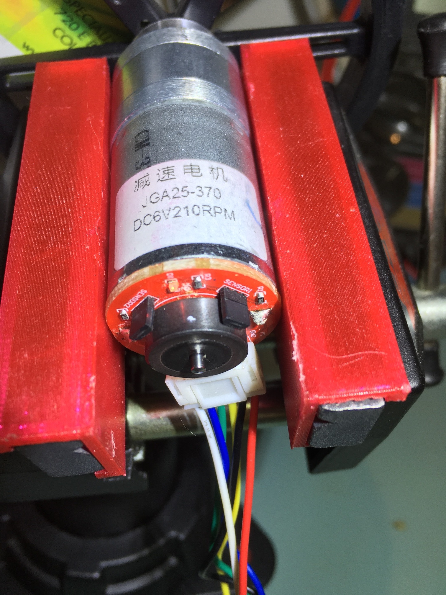
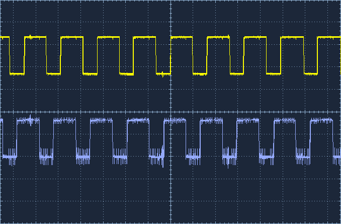
I have a JGA-25 370 6VDC 210 RPM motor with encoder, and I'm trying to figure out what the ratio is between encoder pulses and RPM. I have hooked up the C1 & C2 lines to my O'scope and see nice pulses at about 300 Hz (see scope capture), with the motor running at about 80 RPM.
How do I relate the motor RMP to encoder pulses so I can control motor RPM by measuring encoder timing?
IOW, 80 RPM should produce some integer multiple of encoder pulses, but I'm having trouble figuring what that integer is.
80 RPM = 80/60 = 1.3333 RPS. 300 pulses/sec / 1.3333 = 225.0005, so 225 encoder pulses per RPM?
It looks like there are only two sensors on the encoder board, so I would expect only 1 pulse per revolution per sensor, so why am I seeing 225? Is this the gear ratio?
Looking at images of the motor on google the encoder is connected to one end of the motor and the other end of the motor connects through a gearbox to the drive shaft.
It seems the gearbox is a 1:34 reduction ratio so the motor speed will be a lot higher (34 times) than the output.
It looks like there are only two sensors on the encoder board, so I would expect only 1 pulse per revolution per sensor, so why am I seeing 225? Is this the gear ratio?
Your scope image did not attach, so its not clear what you see.
You have the gear ratio of the motor and the number of poles on the magnetic disc passing by the sensors. Google searches I tried, yield different specs for the motor/encoder so its not clear what you have.
You can read it as a quadrature encoder and pick up 1x,2x, or 4x the number of pulses depending on which sensors and which pulse edges you read.
I tried to add the image just now, but it doesn't display properly (at least not for me). The URL is a link to my Google Drive site, and it displays fine if I just paste the link into a browser, but not in the post display - ugh!
OK, I got the scope screenshot image up, at least, and I have attached a photo of the motor and encoder.
If I have a 34:1 reduction ratio and the output shaft is doin 80 RPM, then the back shaft should be doing 30*80 = 2720 RPM = 45 HZ. However, my encoder output is more like 300Hz, or about 6 times higher than it should be. So either I'm getting more pulses per rotation (doubtful) or the gear ratio is higher. What do you think?
paynterf:
OK, I got the scope screenshot image up, at least, and I have attached a photo of the motor and encoder.
If I have a 34:1 reduction ratio and the output shaft is doin 80 RPM, then the back shaft should be doing 30*80 = 2720 RPM = 45 HZ. However, my encoder output is more like 300Hz, or about 6 times higher than it should be. So either I'm getting more pulses per rotation (doubtful) or the gear ratio is higher. What do you think?
I discovered a minor hardware problem with the encoder module that was throwing off the calculations. The 'sensor2' Hall effect transistor was bent slightly away from the motor shaft disk, so that it was only producing pulses for about half the rear shaft rotation. When I re-positioned it to the same orientation as the 'sensor1' transistor, I get a much more consistent encoder output, as shown in the attached image.
With the motor turning at an estimated 160RPM, the encoder pulse train frequency was a pretty stable 600Hz.
600Hz = 3600 RPM. Assuming the 34:1 gear ratio is correct, that gives 3600/34 = 105.88 RPM, off by a fair bit. To get to 160RPM the 3600 back-end RPM would have to be divided by 22.5. This all assumes one magnetic pulse per back-end shaft revolution, which may or may not be true, but more magnets makes the numerical problem worse, not better. For 2 magnets, 600Hz works out to 1800RPM, or a gear ratio of 1800/160 = 11.25
Can somebody please check my math, considering I'm still using my Microsoft calculator that gave me 30*80 = 2720 ;-)?
You are getting good looking, pulses from both sensors, spaced well in relationship to each other. You should be able to read the encoder just fine with the standard routines well covered in tutorials.
The number of pulses per revolution is what it is. It's a function of the hardware and will not change. As suggested, turn the motor slowly by hand for one revolution and see what you get.
I have seen some specs for that motor which indicate 11 pulses per revolution.
JCA34F:
Grip the shaft stub gently with pliers and turn it one turn while watching the scope.
I did try that, but I'm using a new Hanmatek DSO and was having trouble interpreting the output. So, I used a DVM and that worked much better.
I very carefully turned the wheel attached to the front shaft and marked the rear shaft disk at each point where the DVM showed a high (3.3) voltage. I did this a couple of times, and determined that there were either 9 or 10 'high' spots on the disk.
With 10 spots and 600Hz encoder pulse frequency that results in 600 * 60 = 36,000 (I slipped a decimal place before) /10 = 3600 RPM at the back. For a gear ratio of 34, that gives about 106 RPM at the front, which is a bit low from the 120 RPM stopwatch-based estimate.
With 9 spots, I get 36000/9 = 4000 RPM at the back and 117.65 RPM at the back - much closer to my estimate. So, I'm guessing 9 spots and a 34:1 gear ratio.
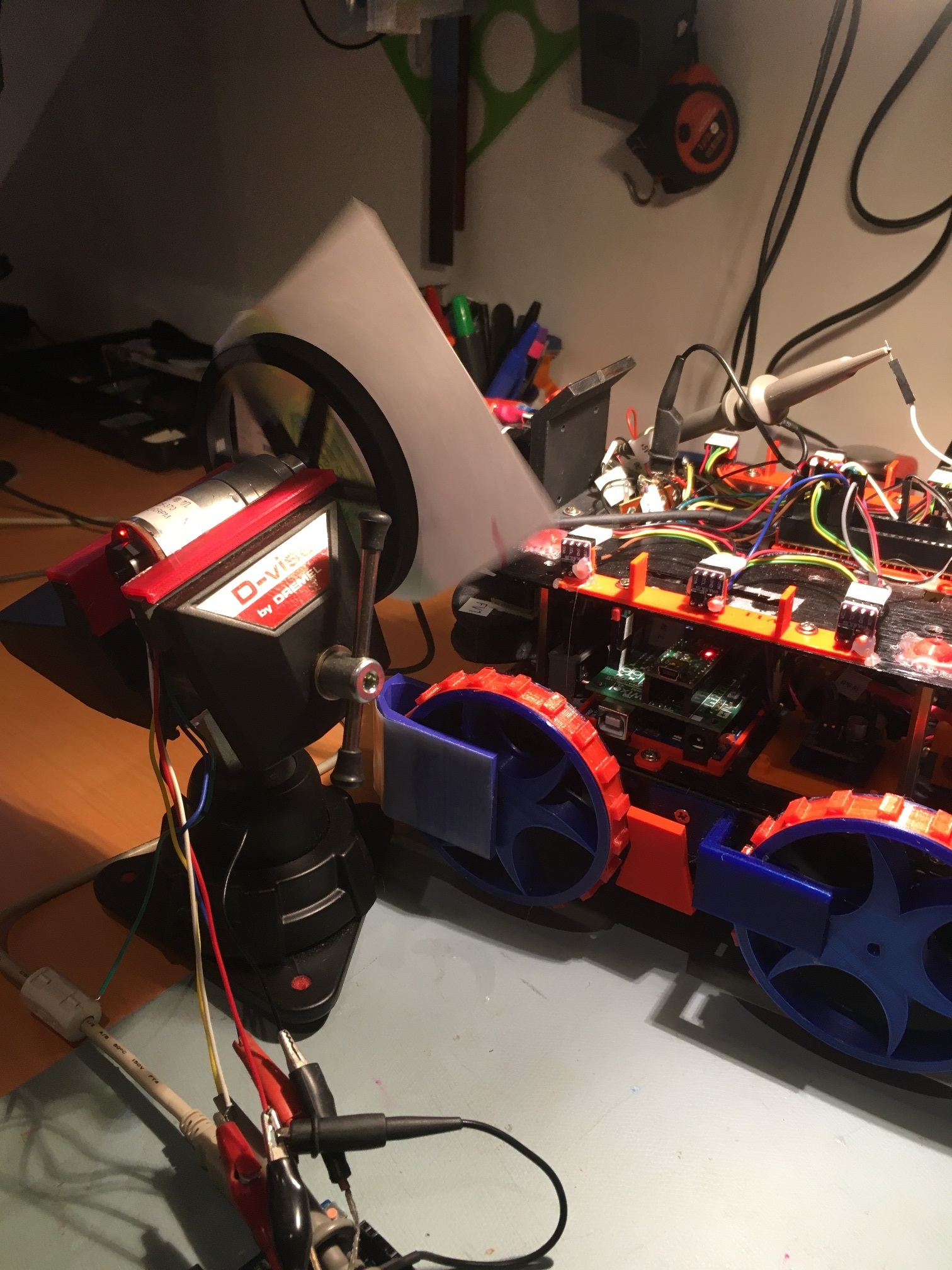
I modified my VL53L0X time-of-flight driver program to implement an optical tachometer function, and used it to directly measure output shaft RPM. Then I adjusted the motor speed to achieve 120 RPM (2 Hz), and I verified this value by physically counting ~60 revs in 30 seconds, so I know I'm close. With this setup I measured the back-end shaft encoder output frequency with a scope and got 473 Hz.
473Hz / 2 = 236.5. I believe this has to be [GEAR RATIO] * [NUMBER OF ENCODER PULSES/REV], so if the gear ratio is 34, then
236.5/34 = 6.956 --> 7 encoder counts / rev?
This doesn't square with my manual encoder count of 9 or 10.
If I use 10 as the real encoder count, then
236.5 / 10 = 23.65 --> Gear ratio?
Using 9 for the encoder count, I get
236.5 / 9 = 26.28 for the gear ratio
Since we know the gear ratio and number of encoders are integers, one of the frequency numbers has to be off. I'm pretty sure the 2 Hz number is close, but probably within a few percent. That leaves the encoder output count but I measured it's frequency with two different frequency counters and got the same number on both - 473 Hz +/-
Talk about "Hard to remember the idea was to drain the swamp when you're up to your tootsie in alligators" syndrome ;-). I started this project with the idea of using a motor turning a flag to measure the response rate of a VL53L0X running in 'fast/continuous' mode, but now I'm deep into the details of DC geared motor design
With this setup I measured the back-end shaft encoder output frequency with a scope and got 473 Hz.
473Hz / 2 = 236.5.
Why are you dividing by two? You should only be counting one channel and one edge of the pulse to determine the count.
If I use 10 as the real encoder count, then
236.5 / 10 = 23.65 --> Gear ratio?
Using 9 for the encoder count, I get
236.5 / 9 = 26.28 for the gear ratio
I would go with the 10 count. It brings the gear ratio closer, and the ratio of a gear train is not going to be perfect in a hobby motor. I have also seen the number 10 for the encoder in some of the motor descriptions on the web.