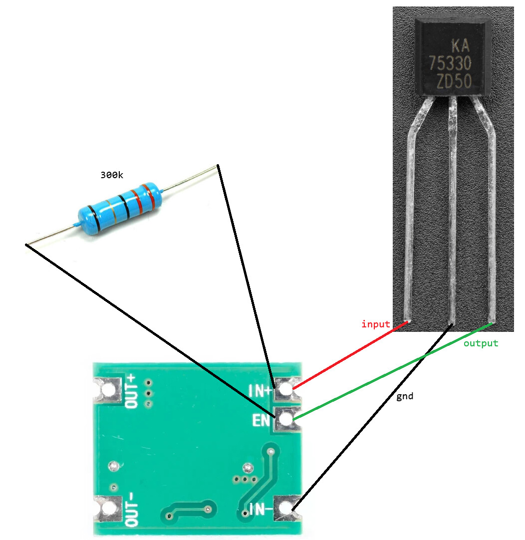
I wired a KA75330 to the Enable pin of a buck/boost voltage regulator (B628 IC), which is powered by a lithium cell, with the intention of making the voltage regulator turn off when the battery discharges down to about 3.30V. The buck/boost module that I'm using exposes the Enable pin, but there is no built-in pull-up on the board, so I added a 300k pull-up which is required to turn on the regulator.
The problem is that the KA75330 is not pulling its output pin low, so the regulator never turns off, and being a buck/boost it will discharge the battery down to 2.00V or less. It went as low as 2.70V when I was testing it.
Looks ok, it should work. I suppose that you have already checked with the tester that the output pin doesn't go to zero.
Maybe the voltage detector is not working. Test it alone with 5V and a potentiometer forming a voltage divider. Check that the output pulls to zero when the input voltage goes below 3.2V (thresold - hysteresis).
The output should be pulled up, as you did. Try with a smaller resistor, about 50K Ohm. Actually it should short output with GND.
That made me look at the circuit again. It's actually the other way round.
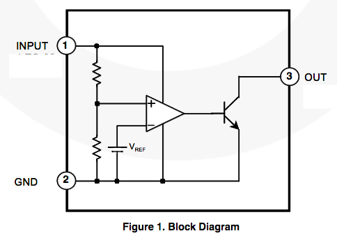
Figure 1 on page 1 of the K75330 datasheet suggests that the output is LOW when the supply is >3.3volt. So the converter turns off if the battery is higher than 3.3volt and on when the battery is below 3.3volt. The opposite of what OP wants.
Leo..
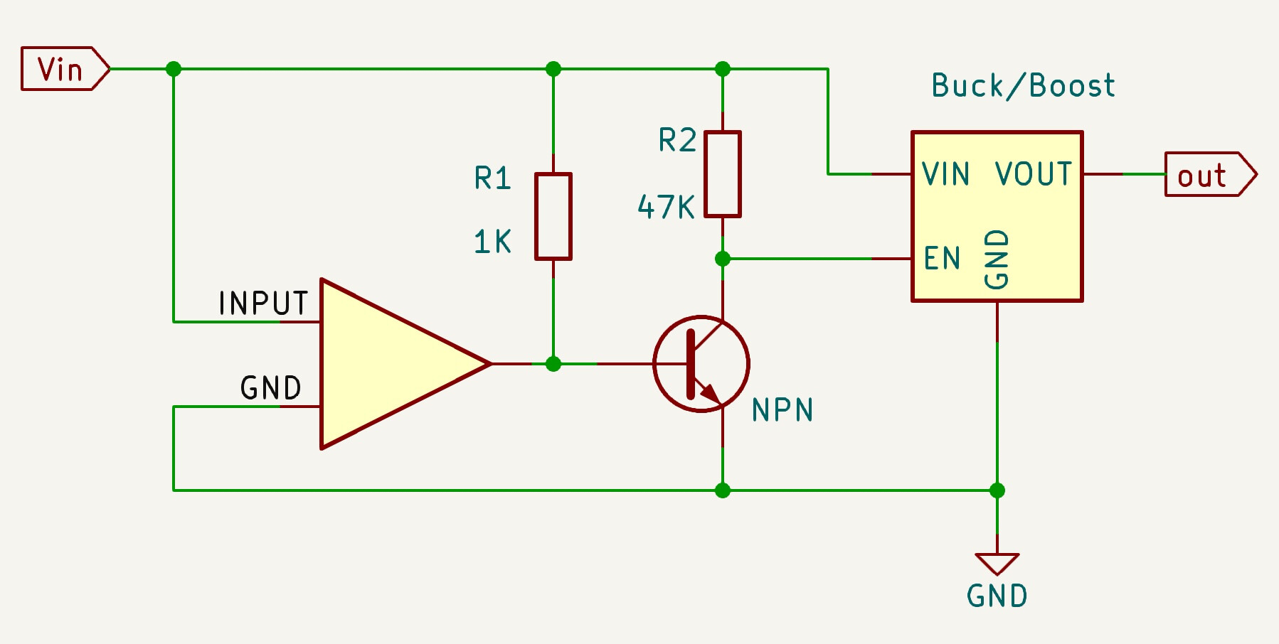
When Vin is above 3.3V, then the output of the detector is connected to GND and the BJT is off, so EN is high.
When Vin goes below 3.3V, then it's output get's floating but tied to Vin and the mosfet will be on, pulling down EN.
(R1 value should be checked)
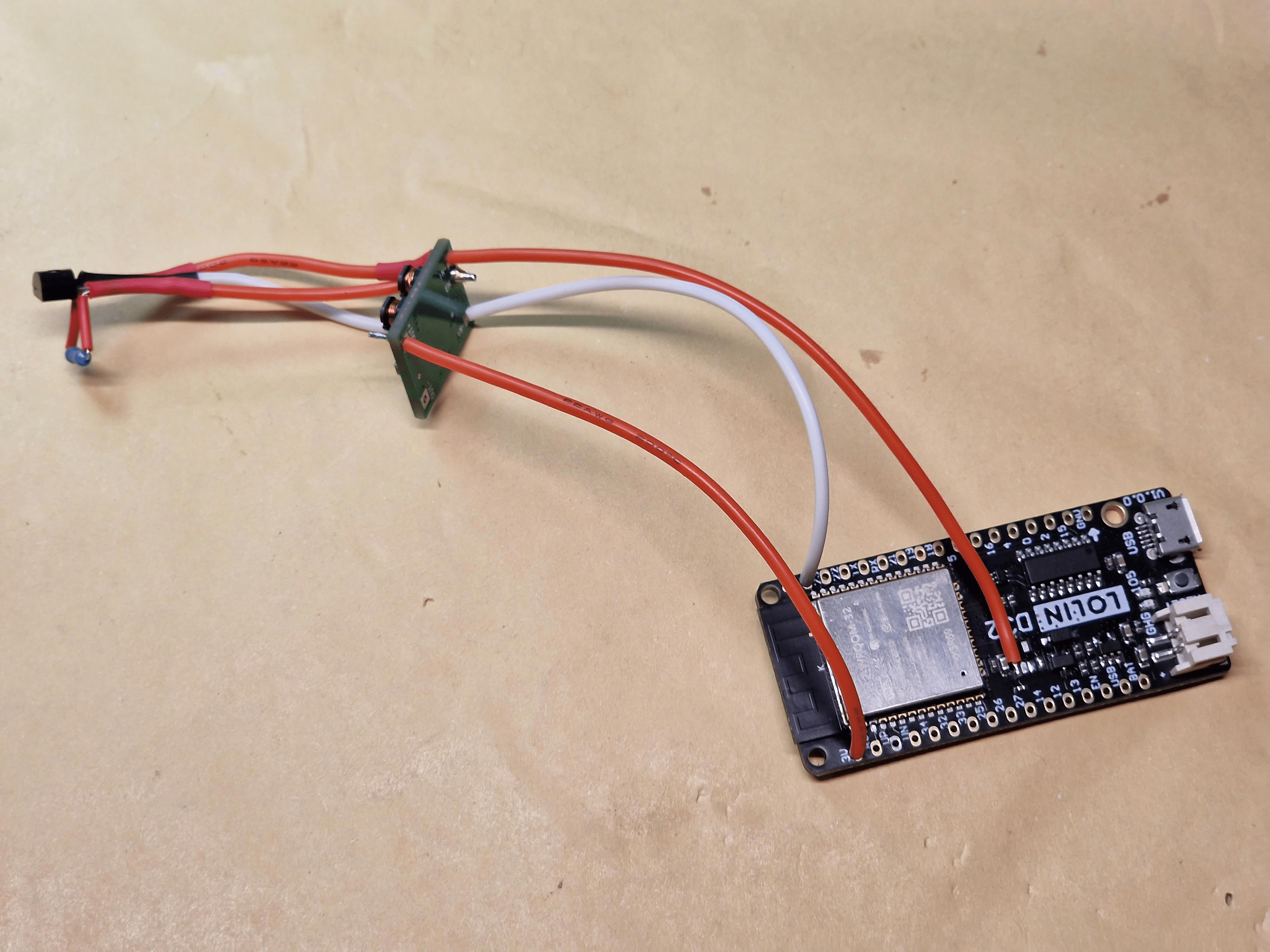
If you have to add a couple more components, first I would connect everything in a breadboard to test and adjust. And draw a proper schematic first, it will make the work easier and less chance to make mistakes.
When it works you can solder the parts in a small perf-board, or without it, dead-bug style like you have now.
If the KA75330 was pulling the output to ground while the input voltage is >3.30V, wouldn't that cause the voltage regulator to shutdown? My pull-up resistor is very weak.
I have twenty KA75330, I grabbed 5 or 6 to test with a AAA cell at ~1.57V and a lithium cell at ~4.10V.
Battery positive to pin #1 (input) and battery negative to pin #2 (ground).
Voltage on pin #3 (output) measures 0V.
Multimeter is resistance mode, measuring between pin #2 (ground) and pin #3 (output);
Black probe on ground and red probe on output measures about 9.8MΩ.
Red probe on ground and black probe on output measures about 4.6MΩ.
The results are exactly the same for both 1.57V and 4.10V, on all 5 or 6 that I tested.
I was measuring from ground to output.
Measuring from input (red probe) to output (black probe) I get 1.035V with the AAA battery and 3.450V with the lithium battery.
Something extrange happens. In your tests with the batteries, for each battery first check the real voltage in the input pin. Then the output voltage.
This would be consistent with the output off, so floating. But when the voltage detector is active the resistance between out and GND should be very low, close to zero.
So, I understand that this should be like this:
with Vin > 3.3V resistance OUT-GND => zero.
with Vin < 3.3V resistance OUT-GND => very high.
Check if it works this way, the opposite or anything else.
The battery's voltage measures exactly the same when connected to the KA75330, there is no voltage sag. I triple checked my measurements for both batteries for each of the KA75330 that I tested.
This little chip is a simple solution: It monitors the voltage on one Input pin, and when that voltage goes below 3.3V, it will pull the Output pin low. If you connect that Output pin to the Enable pin on the Feather, it will make sure that the Huzzah does not run if the battery dips too low.
Build the circuit from figure 4 in the datasheet and start testing (RL can be 1k).
Connect it to a 5volt supply and see if the LED is on or off.
If the LED is on, then Lady Ada is wrong (third video on the page you linked to).
Leo..