Hi ! I have got a L293D IC Based Driver Board in Local market. I want to 2 dc motors with arduino.
Can I use this Driver Board with Arduino? What will be the connection settings with Arduino? Kindly guide me.
Hi ! I have got a L293D IC Based Driver Board in Local market. I want to 2 dc motors with arduino.
Can I use this Driver Board with Arduino? What will be the connection settings with Arduino? Kindly guide me.
Hi !
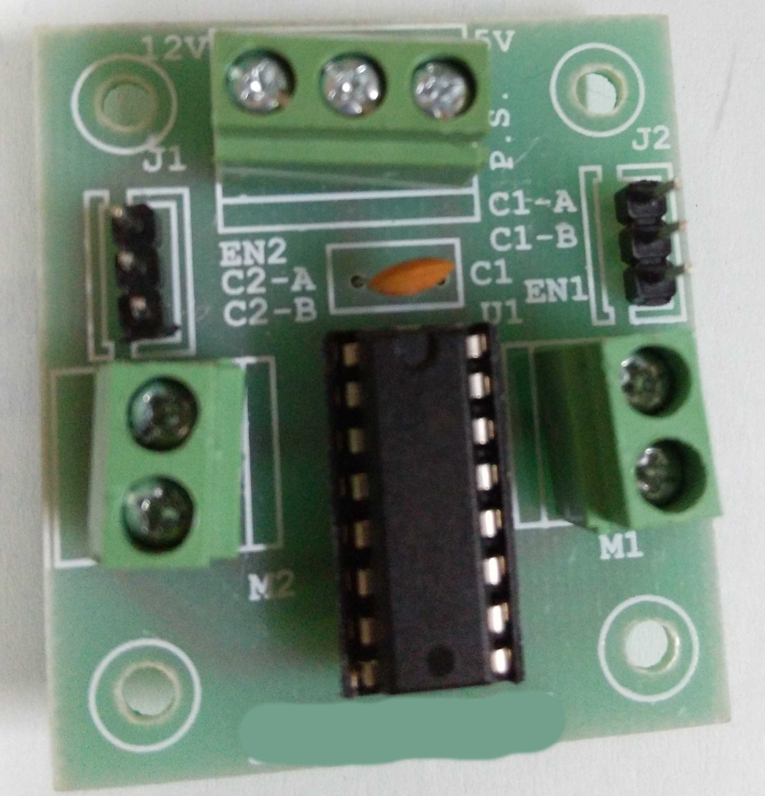
I have got the following L293D Motor Driver Board in local Market.
Kindly guide me about the connections I need to make it with Arduino UNO for controlling 2 DC Geared motors.
I have purchased 2 12V DC GEARED MOTORS along with it. I am just starter if you can guide me.
I think if you read the L293 datasheet it should be fairly obvious.
...R
Thank for replying Robin2. But the datasheet explains the L293 IC connections.
I need to understand this board's connection.
Major confusion for me is how to power this board ?
and
secondly if I don't want to use PWM, i can ignore en1 and en2. But which pins to connect with c1-a,c1-b,c2-a,c2-b?
Who is the manufacturer? What is written on the end of the board and covered?
M1 and M2 are obviously the motor connections for each motor. 12v and 5v are obviously power inputs.
Presumably ( as we cannot see) the centre of the power input is the ground.
En is enable the motor. A and B inputs are possibly direction and PWM. Without documentation we cannot be sure.
The header inputs would be logic level inputs.
The 12v is to power the motors. Note that the H bridge drops a few volts so the motor would receive about 9v.
You will have to experiment to see what logic level does what.
Weedpharma
This is a double post. More wasted time!!
Weedpharma
Don't bother replying. This is a double post.
Weedpharma
Note the two,threads have now been combined!
Thank you weedpharma...
I got the device with me now. I will experiment with it regarding logic.
jpsbhullar:
Thank for replying Robin2. But the datasheet explains the L293 IC connections.
I need to understand this board's connection.
Don't the connection names written on the board match the names in the datasheet ?
...R
Robin2:
Don't the connection names written on the board match the names in the datasheet ?...R
I am confused about the GND part on the board. Like I have 12v DC adapter. +ve signal will be attached to 12v point. 5v point will be connected to arduino 5v. en1 will connect to PWM pin and then a and b will be connected to 2 pins on arduino. I have to supply signal to a and b like a is HIGH and b is LOW and motor should rotate.
But my question is what to do with GND? will it be connected to GND on arduino BOARD. and where -ve point of 12v adapter will be connected.?
All the GNDs should be connected together.
...R
Robin2:
All the GNDs should be connected together....R
Robin ! I think you are not getting my point.
There is only one GND point between 12v and 5v on board (see the picture above). If I connect GND of motor board to GND of arduino, still I am left with -ve cable unattended. Where to plug in this -ve point of 12v DC adapter?
Hi
gnd of aduino and gnd of motor board and -ve (gnd) of 12V DC adapter, all connected together.
The -ve of your 12V supply is the gnd reference of that supply.
Tom.... ![]()
jpsbhullar:
Robin ! I think you are not getting my point.There is only one GND point
That's why I said connect them together ![]()
...R
TomGeorge:
Hi
gnd of aduino and gnd of motor board and -ve (gnd) of 12V DC adapter, all connected together.
The -ve of your 12V supply is the gnd reference of that supply.Tom....
Thank you. It worked for me.
Now I am able to make one motor work. But the problem I am facing it is not rotating both ways. I am not using en1 pin because I don't want speed control. I am passing three set of values : [0,1], [0,0],[1,0] with delay(1000). So it should be like clockwise, stop,anticlockwise.
But it is not going anticlockwise.
What can be the reason?
First check with a multimeter that the signals are getting to the board.