it's my first post here. I am pretty advanced in mechanical stuff but not that advance regarding electronics. (Even if I already did small arduino projects like stepper motor drivers successfully)
My issue:
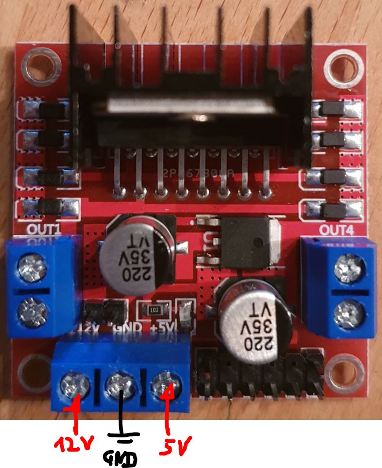
I'd like to position control a simple geared 12V DC motor with encoder via an L298N H-bridge. I connected everything as in the picture below and also understand it (at least I thought so).
--> Arduino is powered via USB
--> Arduino code is also clear and the encoder and outputs are also working according serial monitor.
--> External power supply for the motor is a standard 12V plug in transformer
--> My first Nano immediatly died after first motor revolutions to reach the given target.
I got more careful with the second one and measured if there is a potiential / difference between the motor power ground and the USB ground
--> the red circeled (picture below) is not connected currently: I am measuring nearly 5V difference
--> if I connect both grounds my arduino immediatly dies (yes, I did the same failure 2 times)
Basic question: Why do I have so different ground levels? I never had this sort of issue before with stepper divers for example.
Any help or suspicions are appreciated
additional info: The jumper from the L298N is removed so that I supply the logic 5V to the H-bridge from the arduino.
Do you have a link to the data sheet or manual for that motor driver? Usually those drivers get 2 supply voltages. The motor supply voltage Vm) and the logic voltage (Vcc). I see only Vm connected to Vcc. Is that right?
it's an electronic plug in transformer. I just made a picture. Most of my projects with wired power supply are done with this sort of power supply. It is connected to 12V and GND of the L298N
Regarding the L298N: It is this one L298N
to the motor:
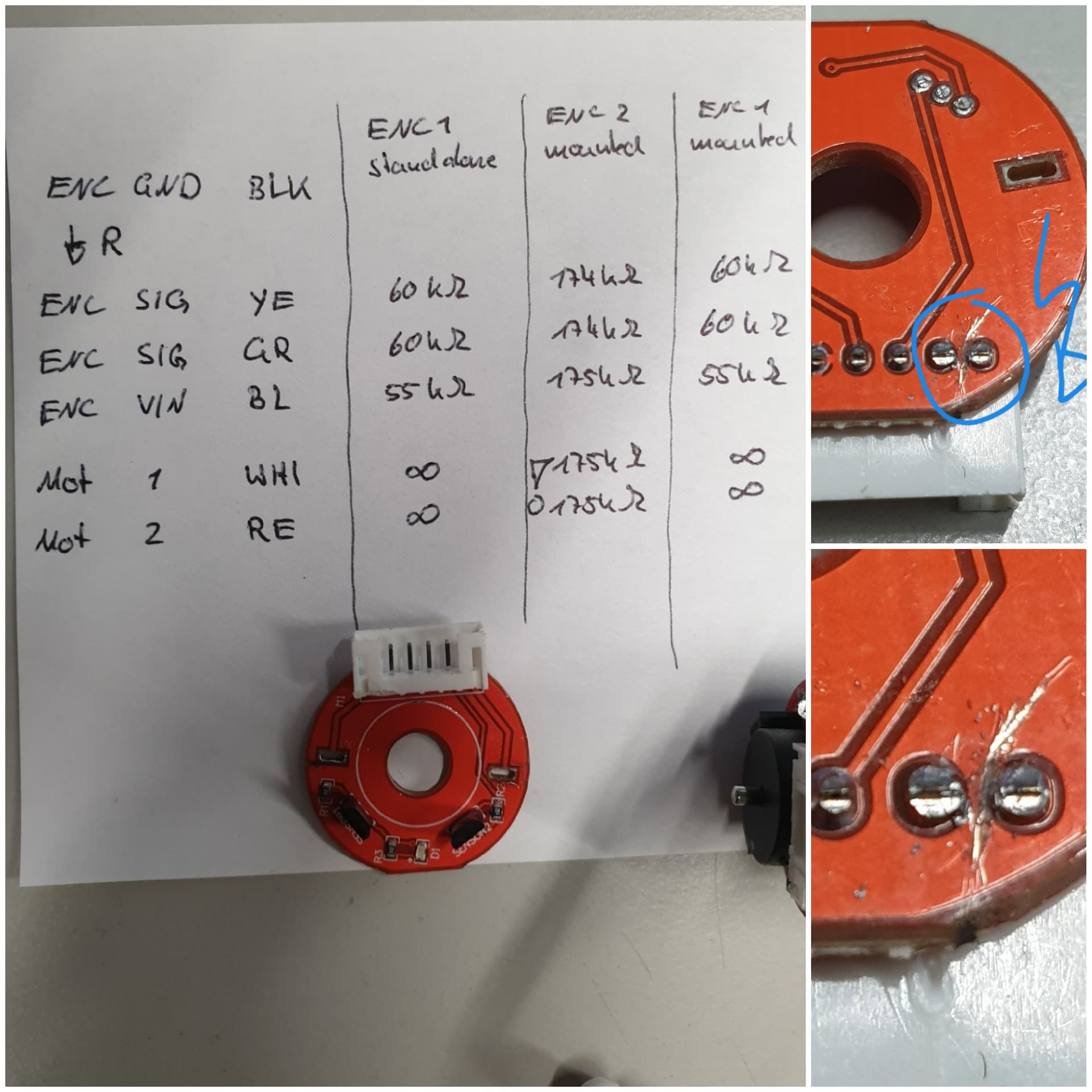
it is a 12V DC motor with encoder. Encoder signal wires are green and yellow, encoder power supply are blue and black (on the motor directly)
--> the encoder is working properly, the arduino code is counting up and down as it should be.
A transformer provides AC, your PSU provides 12V DC. That makes an important difference to me.
Connect the motor power only and directly to the driver board. Also connect Arduino GND to the board GND, so that no motor current can flow through a digital GND wire.
Make sure that the encoder is isolated from the motor wires.
I will do and double check both tomorrow. Today I am done... it's really hard to realize that there is something that you have not understood yet.
DrDiettrich: you are right a classic transformer is transforming AC to AC. Just titled it like this without thinking.
Let's see what the battery test will say tomorrow.
Thanks so far guys
A real schematic would also be helpful. Pretty Fritzing pictures are not schematics and many here will not even try to look at your issue if all you provide is a pretty fritzing picture. Pencil and paper work just fine- be sure to label your pins.
ok, issue solved. It was really a faulty encoder "board" on the motor. Never have seen this but I am happy that I am not as silly as I felt the last two days
I uploaded a picture: I measured all motor / encoder pins of two different motors and saw a resistance between motor pins and encoder pins on the motor assembly I have used. After disassembling the encoder from this motor I saw that two pins on the back side had a very small solder bridge in between. After scratching this bridge away (picture) everything was perfect...
Summary: The encoder platine from my cheap charly china motor was soldered wrong and costed me two arduino nanos...
Thanks to all of you for checking and your good will. You are right Steve, I should have generated a clear schematic. I was a bit unpaitent because of this strange failure.
updated the picture for better understanding. Measured always from ground encoder to all other pins: