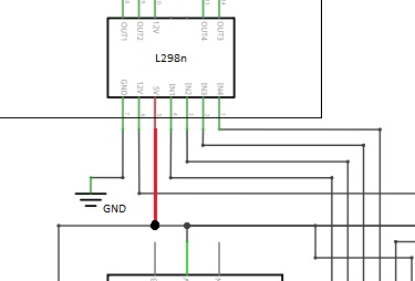
L298n module

Hi,

I drew this scheme of a L298n module thath is connected to an NEMA17 steppenmotor.

Altough I don't think this scheme is correct..

I can't find any L298n module scheme's (thath I understand)

I found this one on wiki

https://www.google.com/search?q=L298n+module+scheme&client=opera&hs=V93&sxsrf=ALeKk01la0Y8vVMEM6yvIYtbNHsiHctmwA:1609510740999&source=lnms&tbm=isch&sa=X&ved=2ahUKEwjts-rf9vrtAhWDHOwKHVsXBEIQ_AUoAXoECBAQAw&biw=1920&bih=1059#imgrc=uhnD6fm-Oye6aMz

Are these all diode's? I thought the L298n had transistors too?

Hi,
Please read the post at the start of any forum , entitled "How to use this Forum".
OR
http://forum.arduino.cc/index.php/topic,148850.0.html.
It will show you how to place images in your posts.
Can you post a complete schematic, including controller and its connections?
What model Arduino are you using?
Can you post link to specs of stepper, Nema17 only tells us its shape, not electrical specs.
OPs Schematic;


Thanks.. Tom.. :slight_smile:

Hi,
L298N are very inefficient and if your stepper needs current control it cannot provide it.
How are you powering your project and in particular the stepper motor?

Tom.. :slight_smile:

Hi,

This is the exact steppen motor I use : Stappenmotor - NEMA17 - 12V 350mA
Its being powered by a 12V supply

Full scheme is also here (I could not find how to add files...)

Hi,
Ops circuit

Code ?
Try this sketch:

/*

 
 This demo uses a L298N dual H-bridge to operate a
 bi-polar stepper motor. The colors are the actual
 color of the wires on several units removed from
 junk printers. 
 
 Numbers such as Pm425-048 and Pm35s-048.
 
 This also worked on a unipolar stepper such
 as a Portescape s6mo48 from Ebay leaving the red/green
 wires that went to +12 disconnected and operating at 24 volts.
 
*/


#define CW 2
#define CCW 3

#define ENA 8
#define ENB 13

#define black 9  // In1
#define brown 10  // In2
#define orange 11  // In3
#define yellow 12  // In4


void setup()  {

  DDRB = 0x3f; // Digital pins 8-13 output
  PORTB = 0x00; // all outputs Dp8-13 set to off
  
  pinMode(CW, INPUT);
  pinMode(CCW, INPUT);

  digitalWrite(CW, 1); // pullup on
  digitalWrite(CCW,1); // pullup on
 
  
}


void loop() {

  if (!digitalRead(CW)) forward(480, 0);
  if (!digitalRead(CCW)) reverse(480, 0);


} // end loop


void reverse(int i, int j) {

  // Pin 8 Enable A Pin 13 Enable B on
  digitalWrite(ENA, HIGH);
  digitalWrite(ENB, HIGH);

  j = j + 10;
  while (1)   {

    digitalWrite(black, 0);
    digitalWrite(brown, 1);
    digitalWrite(orange, 1);
    digitalWrite(yellow, 0);
    delay(j);  
    i--;
    if (i < 1) break;


    digitalWrite(black, 0);
    digitalWrite(brown, 1);
    digitalWrite(orange, 0);
    digitalWrite(yellow, 1);
    delay(j);
    i--;
    if (i < 1) break;


    digitalWrite(black, 1);
    digitalWrite(brown, 0);
    digitalWrite(orange, 0);
    digitalWrite(yellow, 1);
    delay(j);  
    i--;
    if (i < 1) break;

    digitalWrite(black, 1);
    digitalWrite(brown, 0);
    digitalWrite(orange, 1);
    digitalWrite(yellow, 0);
    delay(j);
    i--;
    if (i < 1) break;
  }

  // all outputs to stepper off
  digitalWrite(ENA, LOW);
  digitalWrite(ENB, LOW);

}  // end reverse()


void forward(int i, int j) {

  // Pin 8 Enable A Pin 13 Enable B on
  digitalWrite(ENA, HIGH);
  digitalWrite(ENB, HIGH);

  j = j + 10;
  while (1)   {

    digitalWrite(black, 1);
    digitalWrite(brown, 0);
    digitalWrite(orange, 1);
    digitalWrite(yellow, 0);
    delay(j);
    i--;
    if (i < 1) break; 


    digitalWrite(black, 1);
    digitalWrite(brown, 0);
    digitalWrite(orange, 0);
    digitalWrite(yellow, 1);
    delay(j);  
    i--;
    if (i < 1) break;

    digitalWrite(black, 0);
    digitalWrite(brown, 1);
    digitalWrite(orange, 0);
    digitalWrite(yellow, 1);
    delay(j);
    i--;
    if (i < 1) break;

    digitalWrite(black, 0);
    digitalWrite(brown, 1);
    digitalWrite(orange, 1);
    digitalWrite(yellow, 0);
    delay(j);  
    i--;
    if (i < 1) break;


  }

  // all outputs to stepper off
  digitalWrite(ENA, LOW);
  digitalWrite(ENB, LOW);

}  // end forward()

Hi,
Have you got the 5V pin of the 289 connected to 5V?
This provides power to the 289 logic circuits.

edit456.jpg
This may help;

Have you got a heatsink on the 289?
Tom... :slight_smile:

edit456.jpg

Hi,
Did you write your code in stages.
That is write code;

  • JUST to get the input circuit working.
  • JUST to get the DS3231 circuit working.
  • JUST to get the DHT11 circuit working.
  • JUST to get the Relay circuit working.
  • JUST to get the L289 circuit working.

If you did, have you got working code for the 289, if not, then write some code JUST for the 289 and get it working before adding it to your existing project.

Go to How to use this forum - please read. - Installation & Troubleshooting - Arduino Forum
and scroll down to items 8 and 9.

Thanks.. Tom.. :slight_smile:

TomGeorge:
Hi,
Did you write your code in stages.
That is write code;

  • JUST to get the input circuit working.
  • JUST to get the DS3231 circuit working.
  • JUST to get the DHT11 circuit working.
  • JUST to get the Relay circuit working.
  • JUST to get the L289 circuit working.

If you did, have you got working code for the 289, if not, then write some code JUST for the 289 and get it working before adding it to your existing project.

Go to How to use this forum - please read - Website and Forum - Arduino Forum
and scroll down to items 8 and 9.

Thanks.. Tom.. :slight_smile:

yes, everything works just fine. And the L298n does have a heatsync. But I just need the scheme for it.

Hi,
Is this what you are looking for?
http://wiki.sunfounder.cc/index.php?title=Motor_Driver_Module-L298N

Tom... :slight_smile: