Latching circuit with single GPIO

Hi Folks,

Could somebody explain that circuit (3)?
It's a latching circuit that works with only 1 GPIO.

The whole video is here:

I'm trying to figure out what that circuit does.

Step 1

So this is a P Channel MOSFET there:

When the device is first powered the gate of the MOSFET is pulled high.
So , OK it makes the MOSFET non conductive.

What is the capacitor for here ?

Step 2

As soon as the push button is pushed, it gives a path to ground.

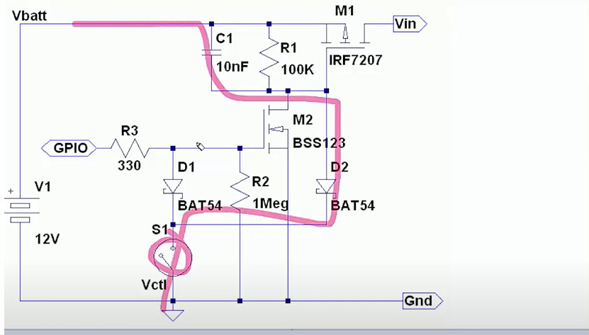
So, OK it makes the P Channel MOSFET conductive because its gate is pulled to low.
So now the current can flow to Vin (and power the Arduino).

Step 3

First line of code of the Arduino would be to activate the GPIO pin as INPUT
and activate the pull-up resistor on that INPUT.

So it pulls up the gate of the N Channel MOSFET.

And that would maintain a path to the ground for the gate of the P Channel (the one on the top). So that P Channel MOSFET would remain conductive.

What is the R3 330Ω for ?
If we use the internal resistor of the Arduino, why do we need it ?

Step 4

It's mentioned the R2 1MegΩ is used to pull the gate of the MOSFET low when the device is off.
So I understand this works as a pulldown resistor to avoid floating input at the gate of the MOSFET.

So, if we have 5V at the pin when the Arduino is on
(with the internal resistor of the Arduino at 50KΩ):


Voltage between R3 and R2 = 5*(1MΩ/(1MΩ + 330Ω +50KΩ) ) = 0.95V


Is that enough to get the gate high when the Arduino is on ?

When the Arduino is off (floating input 5V for instance)


Voltage between R3 and R2 = 5*(1MΩ/(1MΩ + 330Ω) ) = 0.99V


Would that get the gate high when the Arduino is off and there is a floating input at 5V ?

Step 5

When the push button is pressed down again,
it gives a path to the ground.

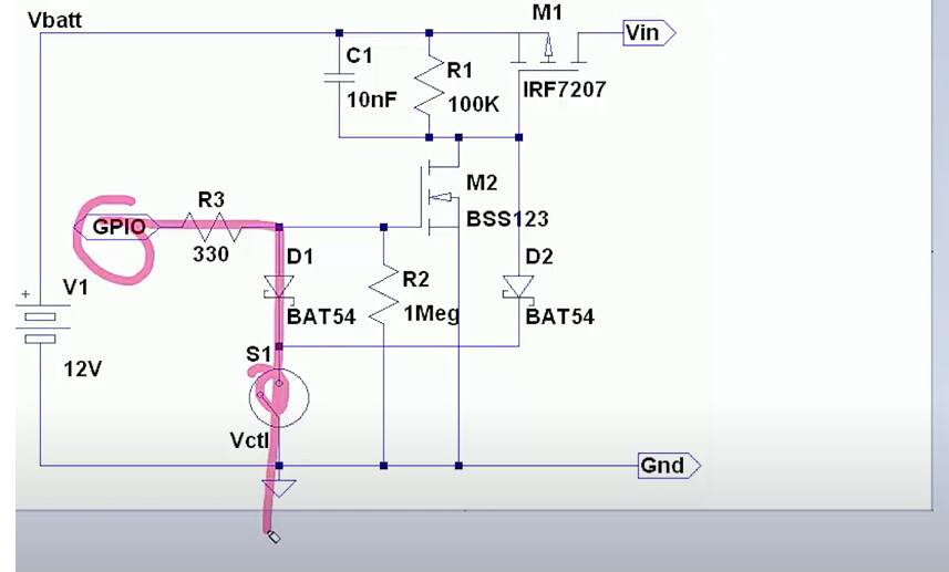
What I don't understand is that it would set the input pin to LOW,
so the gate of the N Channel MOSFET would be pulled down.
And the first MOSFET would be back to non conductive state.

Or maybe the fact that the INPUT put has the internal resistor activated,
it keeps the gate of the N Channel MOSFET activated and
at the same time we can still read the input for the push button as LOW ?

Step 6

When we detect a long press,
we can switch the GPIO as an OUTPUT pin and drive it LOW.
This I understand would pull the gate of the N Channel MOSFET LOW.

So that would stop maintaining a path to the ground for the gate of the P Channel (the one on the top). So that P Channel MOSFET would be non conductive (back to conditions of Step 1).

I would appreciate if somebody could clarify what I'm missing out.
That'd be great.

Thanks.

Cheers!

I think the first thing to do is to clarify what functionality that circuit has before attempting to determine how it works.

It looks like a simple latch where the user presses the push button, 12 volts appears on M1, the Arduino starts (presumably it is powered via the 12v supply) , the Arduino then sustains the latch (by powering M2) and the user can release the button . The 12 volts continues to be present on M1. Some time later, the Arduino, when it has finished its task, will then stop powering M2 and the whole thing switches off.

It appears that the Arduino starts with pin GPIO declared as INPUT_PULLUP, which is just enough to sustain the latch , so it can read the button if required by the application. The Arduino can break the latch by changing the pin GPIO to INPUT.

The circuit itself is a variant of a standard mosfet high side switch.

I didn't see the whole video but the presenter shows a number of circuits with different functionality and this one is rather basic, but with the trick that the Arduino can simultaneously sustain the latch and read the button.

EDIT

  1. The capacitor on M1 looks like a "soft start" device. 10nF is anyway not much higher than the typical gate source capacitance of a power mosfet.

  2. The Arduino pin is initially INPUT_PULLUP which supplies around 5 volts via a ~50k resistor.

  3. The 330 ohm resistor is to protect the arduino pin from the capacitive load presented by the mosfet gate. It is only necessary if pin GPIO is defined as OUTPUT.

  4. Check your calculation again for the potential divider formed by the pullup resistor and the gate pull down resistor. The M2 mosfet gate has not far off 5 volts (the arduino shares a common ground with the rest of the circuit)

  5. Pressing the push button while the latch is maintained by the arduino does put M2 into a non conducive state, however, M1's gate is simultaneously pulled low via D2 so M1 still conducts.

3 Likes

Thanks for the clarification.
I got it now !

I forgot that pressing down the button also gives a path to ground for M1.

When the Arduino is on, the voltage at M2's gate is probably very close to 5V (like 4.999999).
When the Arduino is off,with the R2 resistance being much higher than the input's pin resistance,
the voltage at M2's gate would be too low to activate it.

I think the purpose of C1 is to prevent the mosfet from turning on automatically when power is first connected to the circuit. Without it, the source could immediately go high, but the gate would still be low because the gate capacitance hasn't yet been overcome through the 100K resistor. The capacitor transmits the high voltage to the gate immediately, which prevents any G/S differential developing that would turn on the mosfet.

1 Like

Yes, that is a much better explanation. A "soft start " would anyway require a resistor in series with the gate of M1. As it is, pressing the button would anyway immediately discharge the capacitor, as someone has pointed out to me.

I see ! Like in case the user would change the battery and you don't want this to trigger an auto-start.

Yes, I think so. And it's an open question as to how small the capacitor could be and still work. It only has to raise the gate voltage enough to prevent the G/S differential from reaching the threshold voltage of the mosfet. So it would depend on the threshold voltage and gate capacitance of the mosfet, and I guess on how quickly the power input rises.

I found this Pushbutton On/Off controller:
LTC2954

It's got a delayed start-up function and also a reset function (PDT) in case the controller got stuck.

There are still other components to add around it
but that's a good option I think.

$6 USD. An expensive part and you still need one P MOSFET

I would not know how to implement the reset function (on 6 sec button pressure or more).

Show the code that you are currently using with this latch circuit for ideas on how you could enhance it.

The thing is that I could not use code for this reset function
because it's meant to reset the Arduino in case it got stuck in a loop.

At first I thought I would use the reset button of the Arduino (and push it with a paperclip in the device enclosure for instance) but then I kind of like the idea of having just one button for everything (Start-up, shutdown, user actions and also reset).

This is the function I would like to implement:

image

From this Pushbutton On/Off Controller:
LTC2954


PDT (Pin 7/Pin 6): Power-Down Time Input. A capacitor
to ground determines the additional time (6.4 seconds/μF)
that the pushbutton must be held low before immediately
releasing the EN/EN and INT outputs. Floating this pin
results in a pushbutton power-down time of 64ms.


Integrated in the previous latching circuit I was showing before (for instance):
image

That's the purpose of the Watch Dog Timer WDT.

1 Like

That's a good idea.
I guess with a WDT much longer than the expected duration of a loop
and resetting the timer at the beginning of the loop, that should be fine.

Let's say if you are in an operation of your device where it's doing nothing
but waiting for the user to press down the button to start an operation.
Would that put the device in deep sleep state?
If so, would WDT be deactivated in deep sleep state ?

Not if you wrote the code to plan for that. Generally, update the WDT once every loop(), and don't stall out monitoring anything to ensure the WDT bump happens; it won't care if you bump it every 10 ms, for example.

1 Like

I think I'm sorted then !

I just realized I don't even need a deep sleep mode
because I could trigger low power consumption with a kill signal from the MCU to the the latching circuit.

Using the WDT is in general a good idea but that doesn't help you implement the 6 second long press to turn everything off.

1 Like

The Arduino pin can check the switch just like any other input. So it can put the Arduino asleep on a long press, or can turn the supply off:

and turn off M2 and M1 :slight_smile:

1 Like

That's true but I wanted to implement the 6 second long press reset
as a mechanism in case the MCU gets stuck in a loop.

So I guess with the use of WDT, I'm cover.

That would still be a good idea to implement it
in case maybe the MCU is experiencing another kind of failure that would require a reset.

How long does it take you to recognize that the MCU is stuck? Why then wait another 6 seconds before shutdown?