Hi,
Can you post a circuit diagram of your project please?
Include power supply, component names and pin labels.
A hand drawn image will be fine.
Thanks.. Tom... ![]()
![]()
![]()
![]()
Hi,
Can you post a circuit diagram of your project please?
Include power supply, component names and pin labels.
A hand drawn image will be fine.
Thanks.. Tom... ![]()
![]()
![]()
![]()
Sorry, just give it time and you will be able to.
We do not discuss things privately as the answer to your problem may be exactly what someone else is having difficulty with, and - although it may admittedly be difficult for them to search for the answer - finding the answer to your problem in the public forum could save them going through the process of asking it all over again. ![]()
And I am going to say that the "political correctness" functions of this forum software are continuing to be a right pain in the a**! ![]()
![]()
![]()
![]()
And it has been raining cats and dogs here much of the day, yesterday, a couple of days back and forecast for the next week as well! ![]()
Hi, are you powering up the backlight? 'A' and 'K' pins must be connected to VCC and GND respectively.
The google drive links work just fine for me.
A bit slow but the images came up.
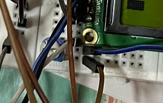
In looking at the photos, it appears that that the soldering of the header pins doesn't look so good.
It looks like there is a small blob of solder up near the edge of the PCB, but the solder didn't melt and fill in the holes.
Yes the 5V is indeed derived from the 5V pin of the Arduino which is powered by Raspberry Pi
What does that mean?
Is there enough 5v power available for that?
--- bill
They do - sort of - "work".
Indeed slow.
The point is that it deliberately prevents you from linking to - or even downloading - the actual image using JavaScript obfuscation. Like many sites such as Aliexpress or eBay. Given time I can extract a genuine link but most of the time it simply isn't worth my time.
The OP appears to be having some trouble with the forum software, sending me PMs in frustration. We'll see if it comes good, my present bet is on that rogue breadboard.
As a 1602 requires only 22 mA for the backlight and 2 mA for the LCD, there should be no problem powering from the UNO, even dare I say it as I always advise against, if powered from "Vin" or the "barrel jack". ![]()
Did you look a the soldering?
It doesn't look so good to me.
And once the LCD does get power, the sketch won't be able to control the LCD given the constructor used.
--- bill
Ok, so I made some changes to my connections after Paul_B told me that the two halves of my breadboard might not be connected. As compared to earlier, when I was getting nothing at all, now all I am getting is a single line of black boxes. No text and backlight. Here is my setup:
#include <LiquidCrystal.h>

LiquidCrystal  LCD(2,3,4,12,9,10);

void setup(){
lcd.begin(16,2);
lcd.write("Hey !!!");
}

void loop(){
}
This is the code I am using.
Can somebody please guide me further after having a look at my latest setup?
Hi,
Can you post a circuit diagram please, a hand drawn image will be fine?
Can you please post some images of your project as it stands now, showing your connections between the controller and the LCD unit?
Thanks.. Tom.... ![]()
![]()
![]()
![]()
Hey, actually I am unable to upload images via the forum.
Here is a drive link to the current state of my setup and LCD unit:
I have also attached my code in a reply above this.
This:
LiquidCrystal LCD(2,3,4,12,9,10);
implies you have wires the LCD like this:
rs=pin2, en=pin3, d4=pin4, d5=pin12, d6=pin9, d7=pin10
It is not easy to see from your pictures if this is the case.
So where is the contrast asjustment pot?
Hi,
Can you please draw your circuit so we can see your connections?
Thanks.. Tom.... ![]()
![]()
![]()
![]()
And it doesn't help that the picture is taken in a dingy half-lit room! (Note the shadows.) It needs to be taken in full daylight. ![]()
If the backlight is not showing - it does not appear to be - then the connections are still wrong. (On virtually all "1602" displays no series resistor is necessary as "R8" on the board is "101" or 100 Ohms.)
Wow, well spotted - almost Easter, you'll do better than me during the egg hunt ![]()
Posting some more images taken in much better lighting. Also attaching a circuit diagram drawn in Tinkercad to show the LCD connections.
Please let me know if these are any better.
Odd connection order - I wonder why?
OK, now these Chinese "Dupont" wires are occasionally faulty. When you do a complete rewire, plug them all into the right hand half of that breadboard so that one goes from one column on the left to a column on the right, the next goes from that right column to a different one on the left, then from that to another column the right and so on. When you just have two ends of that chain left ...
Oh wait, first plug two wires directly from the UNO 5V and ground to pins 15 and 16 on the LCD to see if you can get the backlight to light. If you can, swap the chain I described above to be one of the links that makes it light and see if all the leads are OK.

