Hey folks, I’m new to tinkering with electronics and designing circuit boards.
I’ve looked around online for answers but this community seems like the place someone might know what to do.
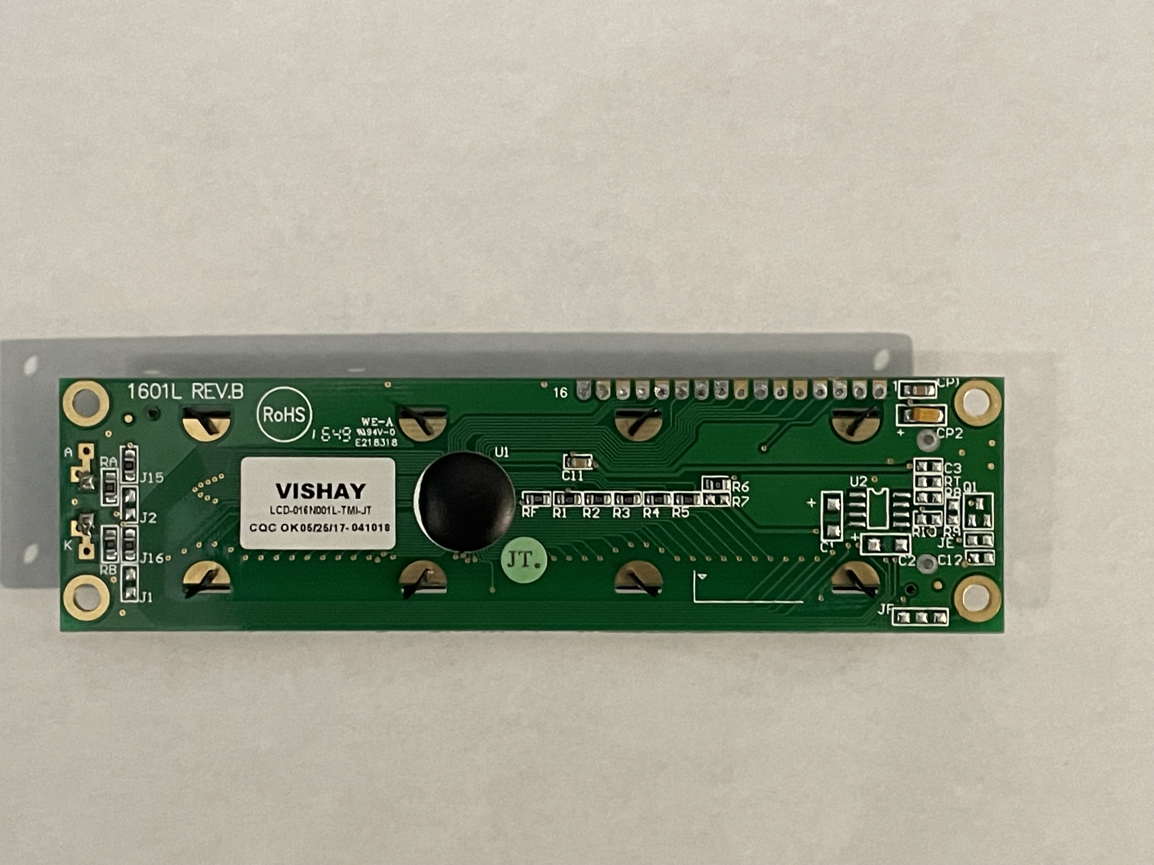
I have a device that I’m trying to “upgrade” that has a 16 character (single row) alphanumeric LCD screen connected to the main board by a 14 pin ribbon cable. This display is +/- 30 years old and I have purchased some new LCD’s that have the same kind of design (Vishay LCD LCD-016N001L-TMI-JT). I’ve connected the 14 pins to the same spots as on the old display and connected it to the board but the display won’t render the characters.
Is there a way to translate the signal coming from the main board to a signal the new LCD will display the same way as the old one?
Given that the new LCD doesn't function correctly, either you made a mistake in the wiring, or it is not compatible with the old display. What gave you the impression that it is "the same kind of design"?
Displays on commercial products are usually custom designed, and in that case, it is almost impossible to find any information on how they are wired or configured. Reverse engineering is required, which is a lot of work.
I get that. I figured where the internal components for everything other than the main board are all third party or off the shelf components there would be a degree of universal compatibility.
What I’m wondering is if there’s a way through a small arduino kit or other component that would take the data coming from the connector on the board and jumble it around and send it up to the new display in a the way it reads input.
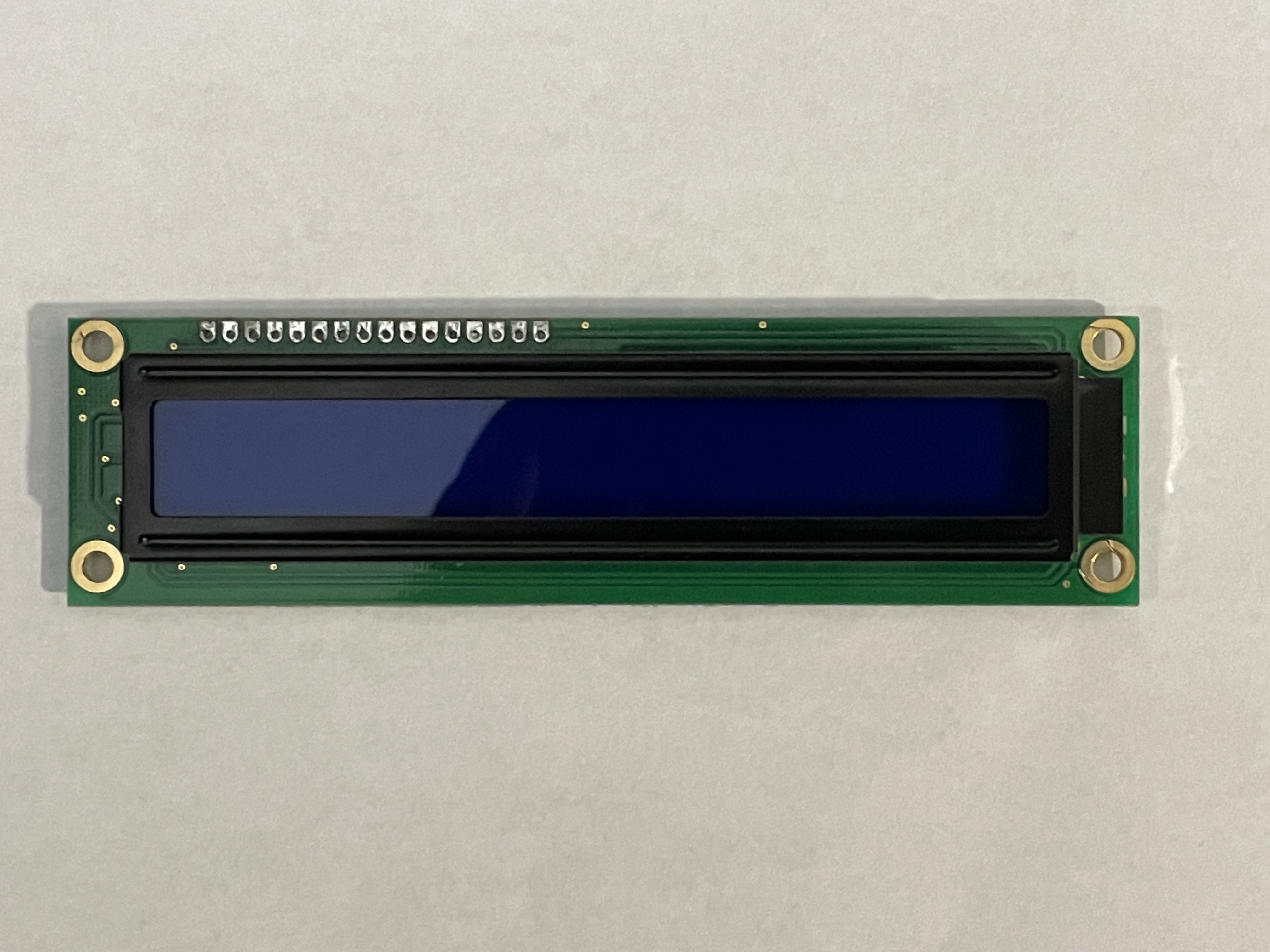
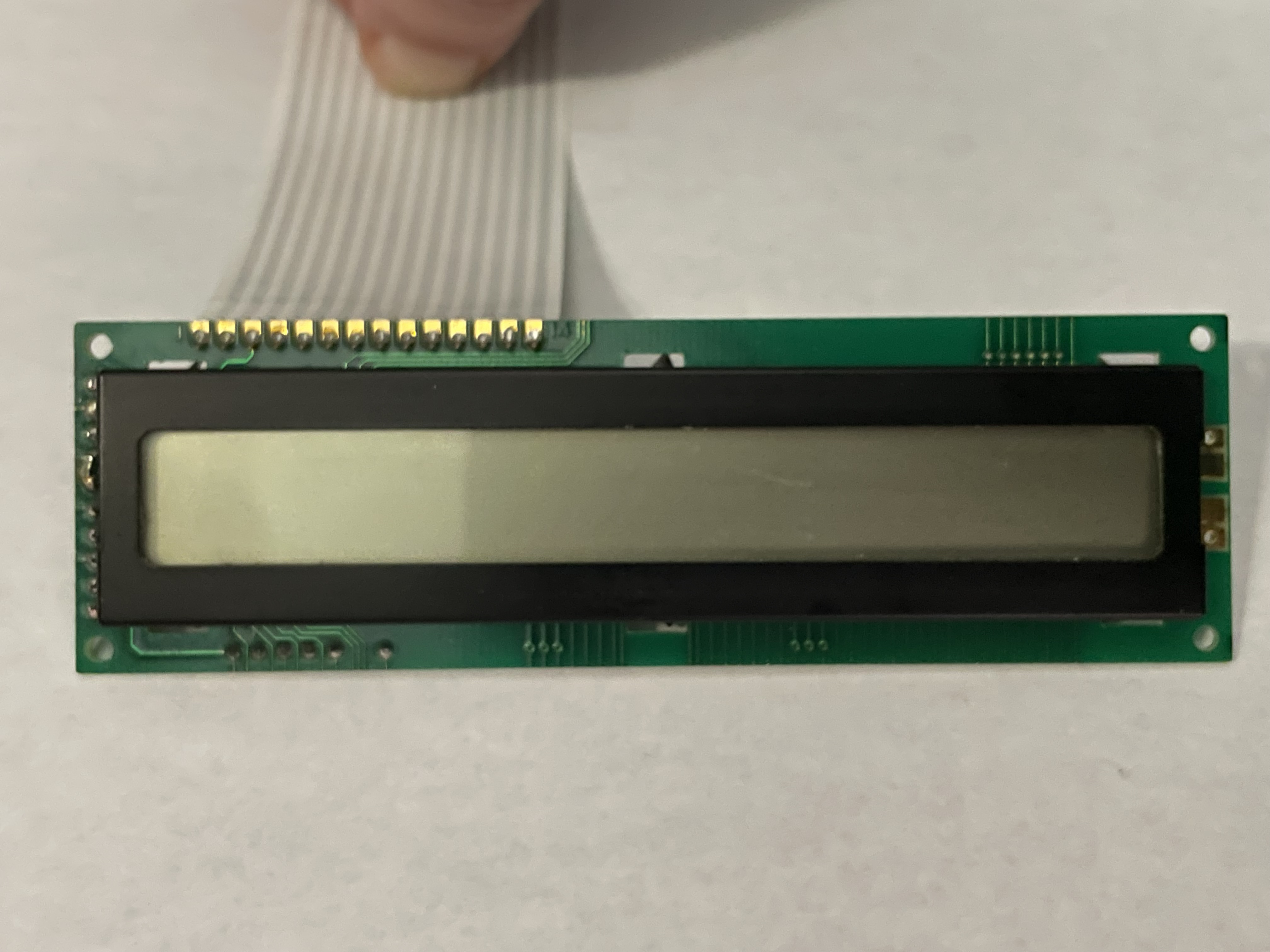
These are the old display (the one with the attached ribbon cable) and the new display (with the dark blue face). Both displays use 14 pins for connection and the extra two pins (15&16) on the new display are the 5v positive and ground for the backlight (as the old display does not have a backlight)
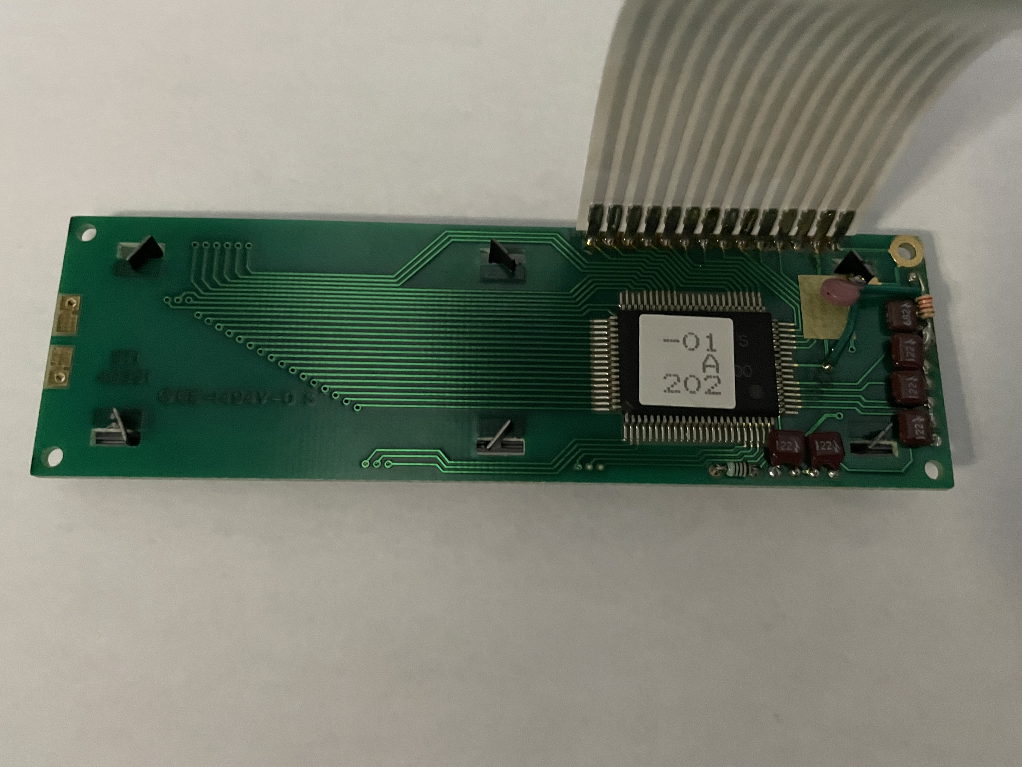
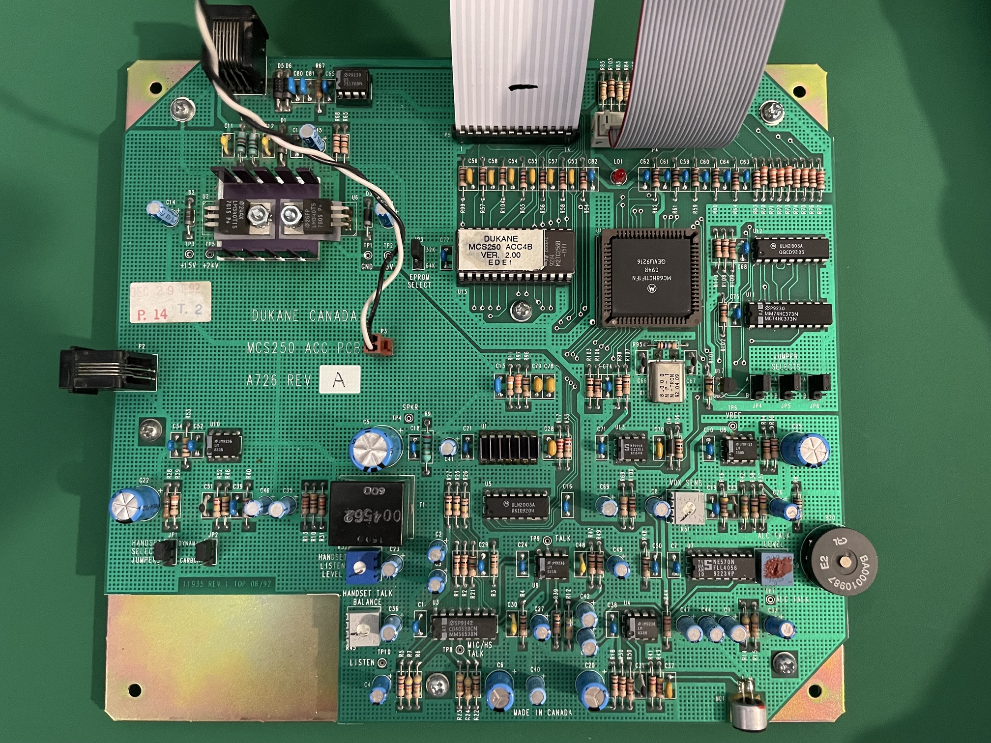
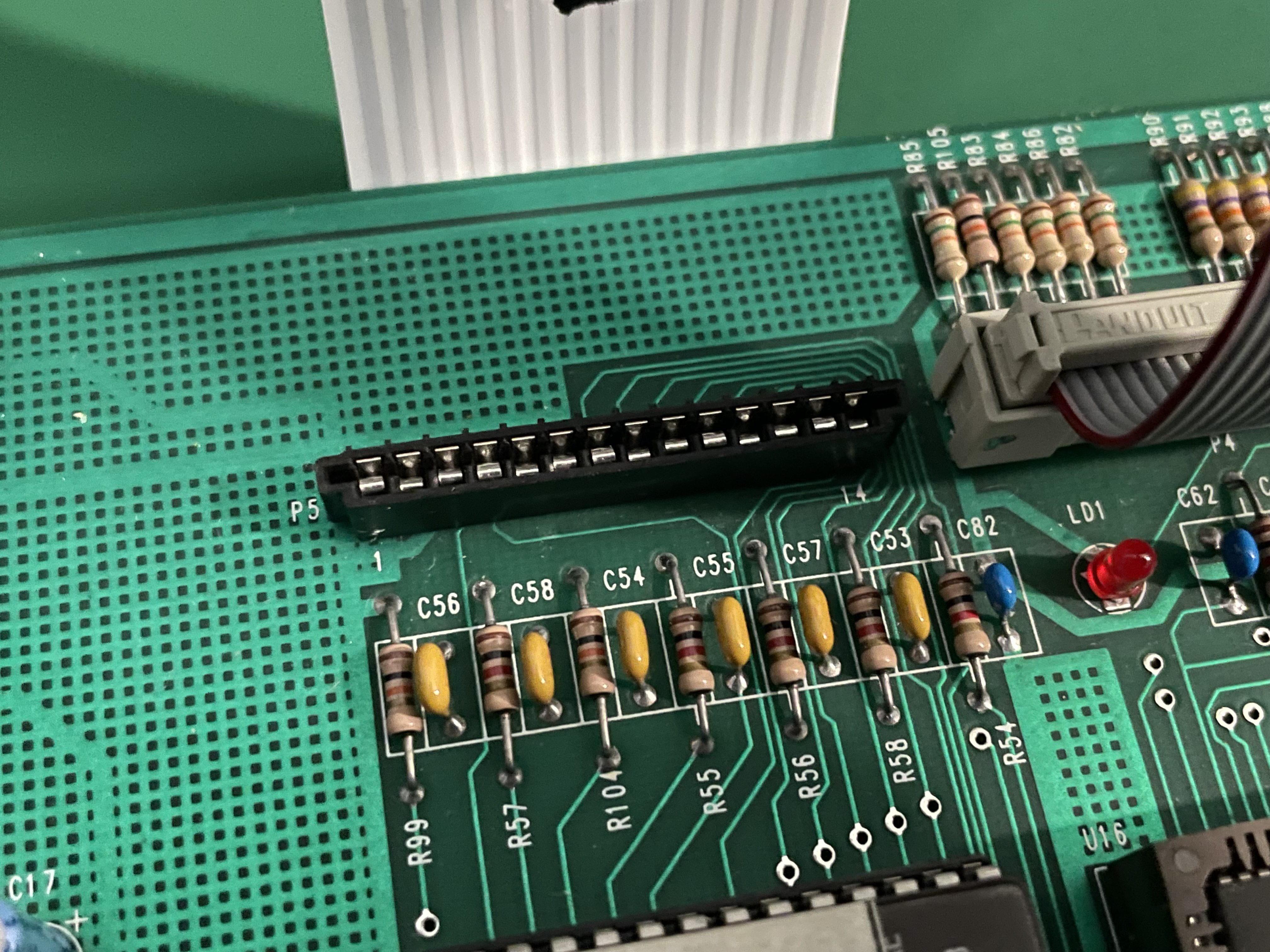
The last two images are the entire main board the display is connected to and a close up of the display ribbon cable connector which I’ve unplugged the display from so the circuits can be seen.
Why are you replacing the old display? Is it not working? Have you tested the old display another way to make sure it is a display problem?
Both your old and new display appear to be a standard display where they went for cheap and made a 16X1 display by using the 8X2 mode of the controller. Both displays have a single controller chip. To get a true 16X2 you need two controller chips. If you look at the spec sheet for you new display on page 9 you see the display addresses jump to x40 for character 9.
The old display works fine. I’m remanufacturing consoles for a communications system that’s been discontinued for about 20 years. New housings, keypad design and a backlit negative transmission display are part of the design.
That’s why I’m trying to get a new display to work with the old consoles from the 90’s. Every console the company made for any of their systems from 1984-2006 (when the company ceased to exist) had a single line 16 character alphanumeric LCD. Which is why I’m trying to get these displays to work with it. So far I can only get the first 8 characters to come up as solid blocks, but when the new display is connected and displaying the blocks it freezes up the rest of the unit and causes all the function LEDs on its keypad to come on while the keypad remains unresponsive.
As suggested by @noiasca see if you can remove the sticker and find a part number. If it is the typical HD44780 see if the interface pins to the chip match what is in page 2 of the new display spec sheet. The interface may not have been as standard back then. Sparkfun has a data sheet here
Look in the lower left corner on page 4 or 5 (depending on which version you have) to see the interface connections.
There are couple of things you need to watch out for when using 16x1 displays.
All are not the same.
Some are really 8x2 displays with all 16 characters on the same line of the physical LCD.But internally the display is really an 8x2 display.
This causes the DDRAM ram addresses for the first 8 characters to not be contiguous with the 2nd 8 characters.
And then some of LCDs are actually 16x1 displays where all DDRAM address for all 16 characters are contiguous.
see this for more about this:
According to the Vishay datasheet for the new LCD, it is a 8x2 display.
The LCD DDRAM address issue should not cause any sort of operational issues with the host processor, but it will cause the display to not display characters correctly if the host is expecting different addressing than the device uses.
Then there are some older LCDs that use a slightly different pinout.
They shift the pins around a bit.
This will cause operational issues.
Make sure that the pinout for the original LCD and the new LCD have the same pinout. You may have to look closely at the PCB boards and traces to figure verify this.
The original display only has 14 pins.
Does the original LCD have a backlight?
How are you wiring up power for the backlight for new LCD?
The datasheet for the vishay shows it uses LOTS of power for the backlight. 160ma that's quite a bit of power, especially for for a 16x1 display. These are typically more in the 20 to 40ma range and some as low as 3 or 4ma.
Maybe the console can't provide that much power.
Great picture! I could trace all the connections to the FB-80B package pinout and they matched the VISAHY layout. Pin 3 is the contrast pin and on the old board is connected on the top.
As I said before they both are 8X2 displays physically configured as 16X1. The 8 blocks you see are line 1 of the display.
I would suggest you try varying the voltage on pin 3 and see if you can get characters to display. The new display may require a different voltage than the old one.