LCD doesn't work

My LCD doesn't work, can you help me?

#include<LiquidCrystal.h>

LiquidCrystal lcd(12, 11, 5, 4, 3, 2);

void setup()
{
 lcd.begin(16, 2); 
}

void loop()
{
  lcd.setCursor(0,0);          
  lcd.print(" HI "); 
  lcd.setCursor(2,1);           
  lcd.print("WORLD!");    
}

in simulation?
do this connections
изображение

1 Like

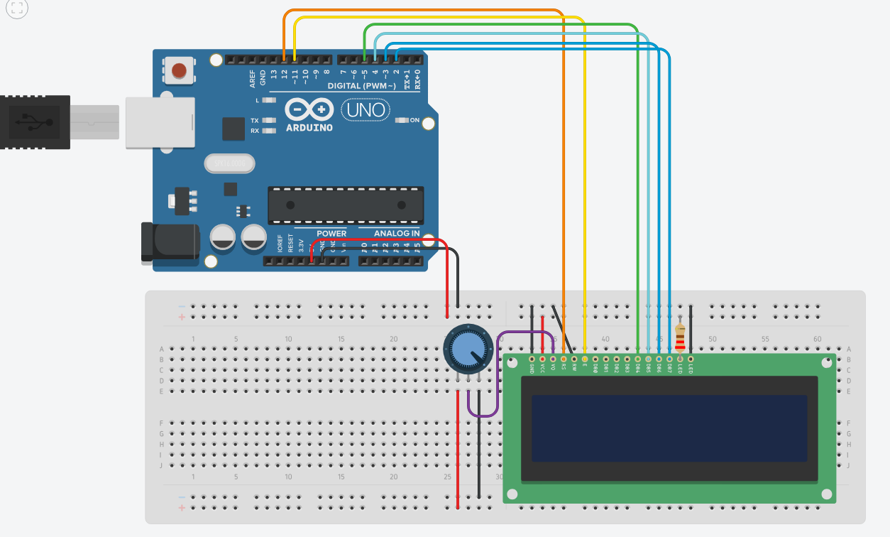
could you tell me how to put a relay in this project on tinkercad? tell me the best cable and code for a relay according to the project I got from Internet. If you can also tell me if the circuit is right. telling me if all the components are needed.

The code of the project from Internet:

#include <Time.h>
#include <TimeLib.h>
#include <LiquidCrystal.h>
 
 
#define LM35pin 0 // connect LM35 Vout pin to arduino analog pin 0
#define LM35ref 1 // connect 2x 1N1418 diodes between LM35 ground pin and ground
#define thermistor_pin 3
 
#define btnPin1 11
#define btnPin2 12
 
#define relayPin 8
 
#define LCD_RS 2
#define LCD_EN 3
#define LCD_D4 4
#define LCD_D5 5
#define LCD_D6 6
#define LCD_D7 7
 
// initialize the library with the numbers of the interface pins
LiquidCrystal lcd(LCD_RS, LCD_EN, LCD_D4, LCD_D5, LCD_D6, LCD_D7);
 
String giorni[7] = {"Dom","Lun","Mar","Mer","Gio","Ven","Sab"};
 
float myTemp = 26.0;
 
int btnState1 = 0;
int lastBtnState1 = 0;
int btnState2 = 0;
int lastBtnState2 = 0;
 
byte iconTermo[8] = {
  B00100,
  B01010,
  B01010,
  B01110,
  B01110,
  B11111,
  B11111,
  B01110
};
 
byte iconDegree[8] = {
  B01000,
  B10100,
  B01000,
  B00011,
  B00100,
  B00100,
  B00011,
  B00000
};
 
byte iconMan[8] = {
  B00100,
  B01010,
  B00100,
  B01110,
  B10101,
  B00100,
  B01010,
  B01010
};
 
void setup()
{
  setTime(23,31,0,10,5,18);
 
  lcd.createChar(0, iconTermo);
  lcd.createChar(1, iconDegree);
  lcd.createChar(2, iconMan);
  lcd.begin(16, 4);
 
  pinMode(btnPin1, INPUT);
  pinMode(btnPin2, INPUT);
  pinMode(relayPin, OUTPUT);
}
 
void loop()
{
  digitalClockDisplay();
 
  // LM35
  float temp2 = readLM35(true); // true = temp in celsius, false = temp in fahrenheit
 
  lcd.setCursor(16, 0);
  lcd.write((byte) 0);
  lcd.print(temp2, 1);
  lcd.write((byte) 1);
 
  lcd.print("    ");
 
  // thermistor
  int sensorValue = analogRead(thermistor_pin);
  float temp3  = Thermistor(sensorValue)/2;
  float temp4 = round(temp3 * 2.0) / 2.0;
 
  lcd.write((byte) 0);
  lcd.print(temp4, 1);
  lcd.write((byte) 1);
 
  // ***** gestisco i pulsanti per regolare la temperatura *****
  // pulsante più
  btnState1 = digitalRead(btnPin1);
 
  if (btnState1 != lastBtnState1)
  {
    if (btnState1 == HIGH)
    {
      // off => on
      myTemp++;
    }
  }
  lastBtnState1 = btnState1;
 
  // pulsante meno
  btnState2 = digitalRead(btnPin2);
 
  if (btnState2 != lastBtnState2)
  {
    if (btnState2 == HIGH)
    {
      // off => on
      myTemp--;
    }
  }
  lastBtnState2 = btnState2;
 
  // temperatura utente
  lcd.setCursor(16,1);
  lcd.write((byte) 2);
  lcd.print(myTemp,1);
  lcd.write((byte) 1);
  lcd.print("       ");
 
  if(myTemp<temp2)
  {
    // accendo la ventola
    lcd.print("ON ");
    digitalWrite(relayPin, LOW);
  }
  else
  {
    lcd.print("OFF");
    digitalWrite(relayPin, HIGH);
  }
 
  delay(100);
}
 
 
/* Legge la temperatura */
float readLM35(boolean celsius)
{
  int analogVal = 0;
  for(int j = 0; j < 10; j++) // takes 10 samples to make sure we get a good value
  {
    analogVal += (analogRead(LM35pin) - analogRead(LM35ref)); // subtract Vout ADC reading from LM35 ground ADC reading
    delay(10);
  }
 
  float tempC = (5 * analogVal * 10) / 1023;
 
  if (celsius)
  {
    return tempC; // return temperature in degrees Celsius
  }
  else
  {
    return (tempC * 9 / 5) + 32; // return temperature in degrees Fahrenheit
  }
}
 
double Thermistor(int RawADC)
{
  double Temp;
  Temp = log(((10240000/RawADC) - 10000));
  Temp = 1 / (0.001129148 + (0.000234125 + (0.0000000876741 * Temp * Temp ))* Temp );
  Temp = Temp - 273.15;            // Convert Kelvin to Celsius
  return Temp;
}
 
void digitalClockDisplay()
{
  lcd.setCursor(0,0);
  lcd.print( giorni[weekday()] );
  lcd.print(" ");
  lcd.print(day());
  lcd.print("/");
  lcd.print(month());
  lcd.print("/");
  lcd.print(year());
 
  lcd.setCursor(0,1);
  lcd.print("    ");
  lcd.print(hour());
  printDigits(minute());
  printDigits(second());
}
 
void printDigits(int digits)
{
  lcd.print(":");
  if(digits < 10)
    lcd.print('0');
  lcd.print(digits);
}

No. Anyone who says they can tell you is lying or guessing. There is no way we can answer your questions.

What we can say is that is that this not the correct way to wire a relay, no matter what the intended use.

if you not able to check that the project fits all your expectation - dump it and make your own. just like this person who share this project.

start by drawing up a project requirements specification
is connecting a relay to tinkercad the complete project or are there other requirements, e.g. sensor inputs, LCD display, WiFi, Bluetooth, etc etc

1 Like

Hi, @barzzixx
Is this part of your project?
https://forum.arduino.cc/t/thermostat-problem-display/1190894

Tom.. :grinning: :+1: :coffee: :australia:

I don't understand why it always remains at the same temperature values, yet if another value is read from the temperature sensor it should print that value on the display and make the LED light up.

#include <LiquidCrystal.h>

#define LM35pin 0 
#define LM35ref 1 
#define thermistor_pin 3

#define btnPin1 11
#define btnPin2 12

#define ledPin 8

#define LCD_RS 0
#define LCD_EN 1
#define LCD_D4 2
#define LCD_D5 3
#define LCD_D6 4
#define LCD_D7 5

LiquidCrystal lcd(LCD_RS, LCD_EN, LCD_D4, LCD_D5, LCD_D6, LCD_D7);

float myTemp = 26.0;

int btnState1 = 0;
int lastBtnState1 = 0;
int btnState2 = 0;
int lastBtnState2 = 0;

byte iconTermo[8] = {
  B00100,
  B01010,
  B01010,
  B01110,
  B01110,
  B11111,
  B11111,
  B01110
};

byte iconDegree[8] = {
  B01000,
  B10100,
  B01000,
  B00011,
  B00100,
  B00100,
  B00011,
  B00000
};

byte iconMan[8] = {
  B00100,
  B01010,
  B00100,
  B01110,
  B10101,
  B00100,
  B01010,
  B01010
};

void setup()
{
  lcd.createChar(0, iconTermo);
  lcd.createChar(1, iconDegree);
  lcd.createChar(2, iconMan);
  lcd.begin(16, 2);

  pinMode(btnPin1, INPUT);
  pinMode(btnPin2, INPUT);
  pinMode(ledPin, OUTPUT);
}

void loop()
{
  float temp2 = readLM35(true);

  lcd.setCursor(0, 0);
  lcd.write((byte) 0);
  lcd.print(temp2, 1);
  lcd.write((byte) 1);

  lcd.print("    ");

  int sensorValue = analogRead(thermistor_pin);
  float temp3  = Thermistor(sensorValue)/2;
  float temp4 = round(temp3 * 2.0) / 2.0;

  lcd.write((byte) 0);
  lcd.print(temp4, 1);
  lcd.write((byte) 1);

  btnState1 = digitalRead(btnPin1);

  if (btnState1 != lastBtnState1)
  {
    if (btnState1 == HIGH)
    {
      myTemp++;
    }
  }
  lastBtnState1 = btnState1;

  btnState2 = digitalRead(btnPin2);

  if (btnState2 != lastBtnState2)
  {
    if (btnState2 == HIGH)
    {
      myTemp--;
    }
  }
  lastBtnState2 = btnState2;

  lcd.setCursor(0,1);
  lcd.write((byte) 2);
  lcd.print(myTemp,1);
  lcd.write((byte) 1);
  lcd.print("       ");

  if(myTemp<temp2)
  {
    lcd.print("ON ");
    digitalWrite(ledPin, HIGH);
  }
  else
  {
    lcd.print("OFF");
    digitalWrite(ledPin, LOW);
  }

  delay(100);
}


float readLM35(boolean celsius)
{
  int analogVal = 0;
  for(int j = 0; j < 10; j++) 
  {
    analogVal += (analogRead(LM35pin) - analogRead(LM35ref));
    delay(10);
  }

  float tempC = (5 * analogVal * 10) / 1023;

  if (celsius)
  {
    return tempC;
  }
  else
  {
    return (tempC * 9 / 5) + 32;
  }
}

double Thermistor(int RawADC)
{
  double Temp;
  Temp = log(((10240000/RawADC) - 10000));
  Temp = 1 / (0.001129148 + (0.000234125 + (0.0000000876741 * Temp * Temp ))* Temp );
  Temp = Temp - 273.15;
  return Temp;
}

Hi, @barzzixx

Can you please post a copy of your circuit, a picture of a hand drawn circuit in jpg, png?
Hand drawn and photographed is perfectly acceptable.
Please include ALL hardware, power supplies, component names and pin labels.
Not a Fritzy image, please.

Thanks... Tom... :grinning: :+1: :coffee: :australia:

@barzzixx,

I have merged your 3 topics, which are pretty much about the same thing. Same project, slightly different questions. The information about one question, and the answers, help the next question so please keep your questions in this one topic.

Multiple new topics about the same thing can lead to a suspension from the forum.

Thank you.

It doesn't work because there are so many errors in your wiring. One error would stop the circuit from working correctly. You made so many errors, I lost count of them.

This circuit is too advanced for your level of experience, you must start with something simple, get that working, then add the next part and so on.

This topic was automatically closed 180 days after the last reply. New replies are no longer allowed.