Dear all, I have this display that I took from a radio equipment that uses the LCD-HD44780 drive, but it has several different characters. Could someone tell me how to program this display? I think it is 16x4 because it has 4 lines of characters.


The information you need is in the data sheet: It can be obtained from here: HD44780 Datasheet(PDF) - Hitachi Semiconductor This is just one of many sources.
Without the datasheet probably impossible to say how the character RAM is mapped to pixels. It quite likely has a special custom character set in ROM.
However, the great thing about displays is you can see the results, if you write data to the screen see what it does.
Oh, I should say try using the HD44780 library.
1 Like
you might check this library and see if it works with that display.
It does not look like a typical LCD display
1 Like
@curcius
as a few others have mentioned,
You have essentially two options.
-
Look at the data sheet for your LCD (best)
-
If it really is a hd44780 interface, hook wire it up as a hd44780 display, use a hd44780 library and start writing to it to figure it out.
You could use the hd44780 library hd44780_pinIO i/o class to control a hd44780 display with Arduino pins.
It will allow you to experiment with various geometries through initalization parameters to the begin() call.
The hd44780 library comes with several sketches including one that will display all the characters in the font rom.
BTW,
Where did you get that partial schematic?
--- bill
1 Like
Thank's i will try this lib
I have no idea where to find the datasheet, I think it will be impossible to program this display. The two libs do not work.
What two libraries are you talking about and what did you try?
Also, Again, where did you get the partial schematic you posted?
You haven't even posted any photos of the display which might show a vendor or part number.
--- bill
Sending: 17399169085763526370213683862649.jpg…
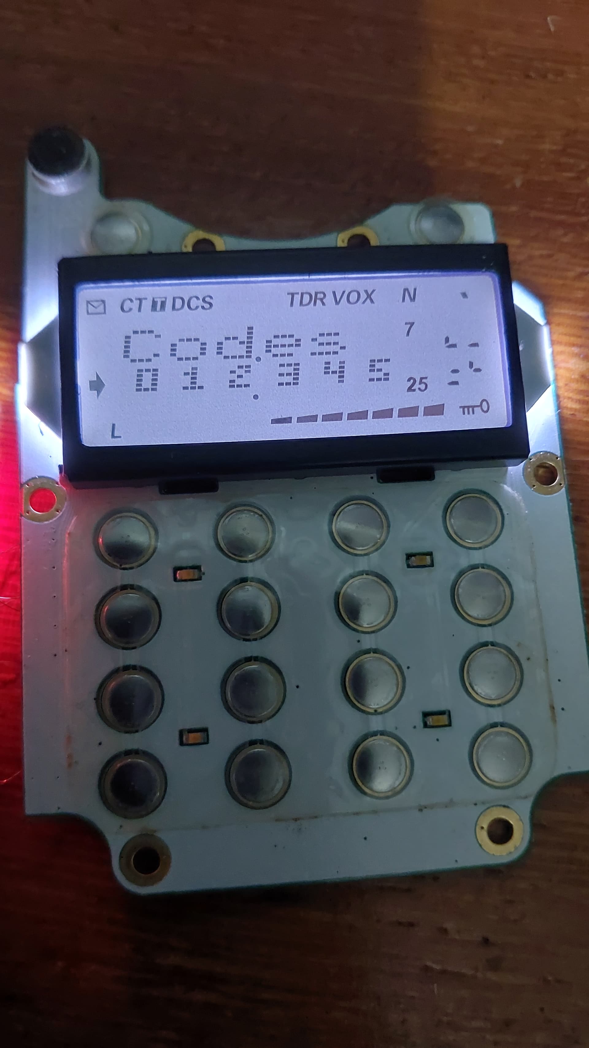
With the HD44780 lib I managed to make some progress but I have no idea how to organize the characters and symbols on this display lol
Can you see the back of the LCD to get a photo of it?
So we can see if there is any vendor or part numbers.
Why do you keep showing us this partial schematic?
It does not fully reflect your h/w, particularly if you are controlling the LCD with Arduino pins.
Where did you get it?
Were you able to display any characters on the display?
If so, time to do some testing to figure out how the display maps its memory to the screen.
The hd44780 library will allow you to cheat and play some games with the setCursor() call by allowing you to set a column off the end of a row.
This is an intential feature.
This allows you to set the DDRAM address by simply using row 0 and the desired DDRAM address for the column.
i.e. use setCursor(DDRAM-address, 0)
This allows you to put a character in any DDRAM address which could be useful in your case to see where things show up on the screen.
I have seen a few hd44780 LCD displays where some DDRAM addresses are "magic" and control icons on the display vs being locations for printable characters.
In the absence of a datasheet, you are in for some experimentation to try to figure things out.
---- bill
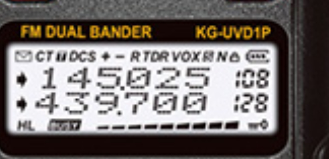
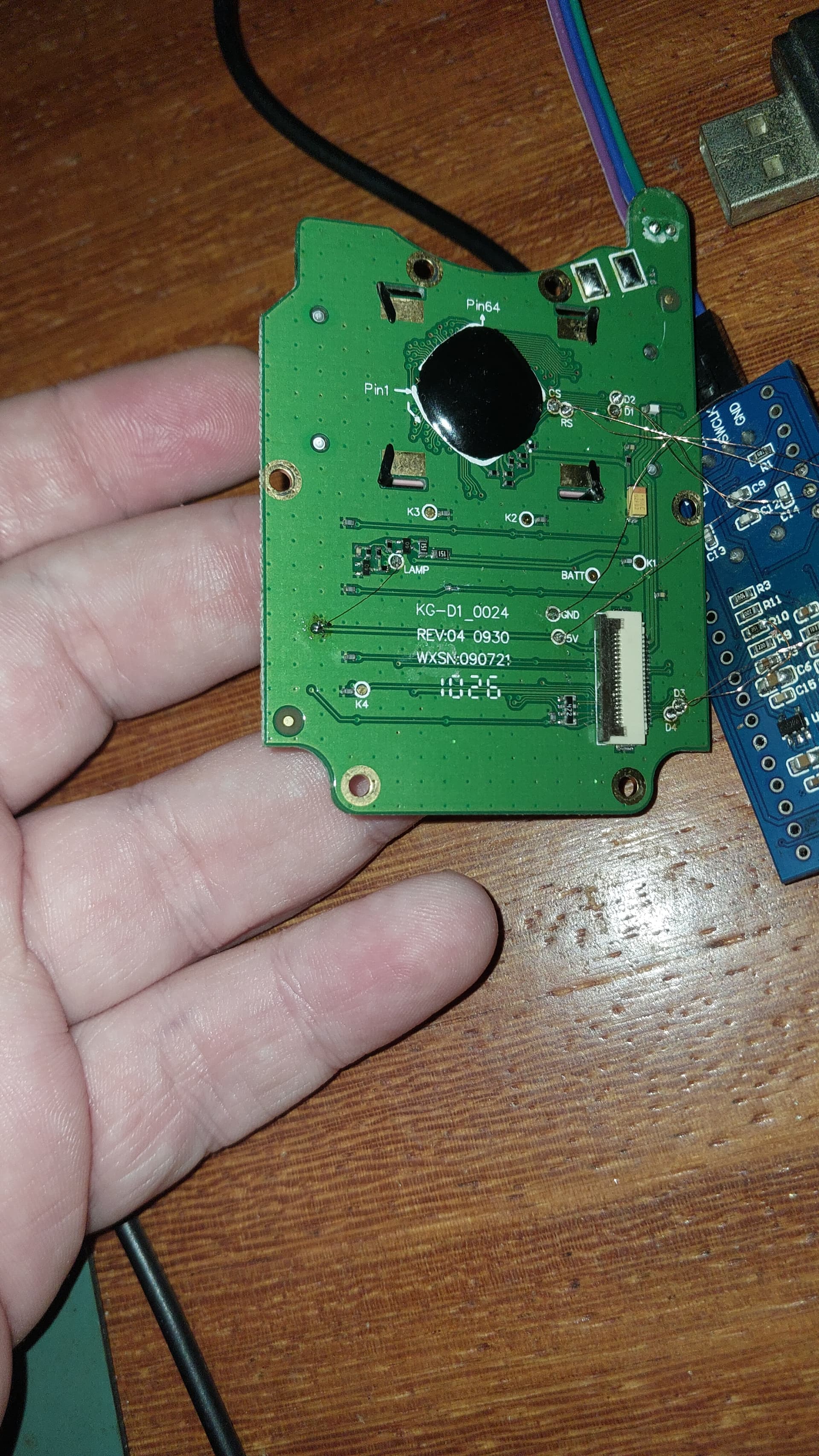
I apologize for the lack of information, it's new for me to try to make a custodied display work, I'm using a bluepill and programming with arduino, about the display it was from a walkie-talkie radio of the Chinese brand wouxun model kg-uvd1p, here's the photo of the back of the display and my setup.
details I managed to discover that I can only write 6 characters on the top line and 6 on the bottom line and if I exceed the 6 characters the symbols light up randomly.

Interesting.
I'm assuming your wires to your blue pill are insulated.
There may only be two lines of 6 characters that can be written.
The other may be special icons.
You can experiment with setCursor() to write to specific locations in DDRAM to see what happens. There are normally 80 locations that can be written to.
I remember one LCD display that had a few icons and they were controlled by writing to magic DDRAM location and then each icon was turned on by a bit in the byte written.
I've seen several LCDs that modify the hd44780 instruction set to add extra configuration options.
This almost always creates issues, the main one being it can affect the reliable 4 bit initialization sequence since they often attempt to steal some unused "must be zero" bits and use them for their new capabilities since they assume "unused" means free for other uses.
It works from a clean power up, but if host nibble sync ever gets lots there is no guarantee the interface can ever get back in sync without a power cycle.
--- bill
How does it power up? Anything on the display?
And what does clear() do?
Does it clear the display of everything after you have written to the display?
note: the hd44780 library does a clear() as part of the initialization done in begin()
--- bill
How do I declare the address with setCursor? Is it in hex? I don't know how to do it, regarding the display when it is powered all the characters light up except line 2, when I use tft.clear it erases all the characters including the icons.
void setup()
{
	// initialize LCD with number of columns and rows:
	//
	// note:
	//	begin() will automatically turn on the backlight if backlight
	// 	control is specified in the lcd object constructor
	//
	lcd.begin(50, 2);

	// if backlight control was specified, the backlight should be on now

	// Print a message to the LCD
 lcd.setCursor(?????, 0);
 }

void loop() {}
I also don't know how to declare tft.begin but I've already tested it and it doesn't interfere. I can declare any rows and columns and the display behaves the same.
For begin()
rows, and cols, are for the library to keep track of and are not sent to the hd44780 chipset.
They don't actually exist in the hd44780 chip. Although the chip does need to know if the display is a single line as that is treated differently.
There is a low level initialization change that happens for 1 row vs more than 1 row.
The library uses cols and rows to calculate the DDRAM address when setCursor() is called.
The chip uses DDRAM addresses to put characters into DDRAM and they show up on the glass however the manufacturer wired up the pixels.
There is also a font size which is an optional 3rd argument to begin()
I would just initialize the display to either 2x16 or 4x20 and then do some testing.
And like I said in post 13, you can use use setCursor(col, row) to directly set the DDRAM address.
Set the row to zero then you can directly set the DDRAM address with the col parameter.
The col parameter is an integer.
You can use decimal, hex, octal, binary, doesn't matter, they are all integers, the only difference is how you enter them.
Use whatever base you want.
But keep in mind there are 80 DDRAM locations inside the chip.
If doing a loop, the loop variable which you could use for the col parameter will be an integer and you loop for as many iterations you want.
You will have to do testing to figure out how the display works with respect to characters, locations, and icons.
I would write a loop to write an incrementing character to all 80 locations to see what happens.
Clear the screen then write 80 characters with a small delay between each one and see what happens.
Another test you could is to have a loop to
set the DDRAM address,
write a character,
have a delay, or wait for a button push, etc..
clear the display
Then you can try all the addresses to see what happens.
My guess is that it is a 2 row LCD and them some magic address(es) (beyond the columns that show on on the LCD) to control the icons. Likely 1 bits in the byte of the magic DDRAM address(es) turn on specific icons.
So once you figure out if there are magic DDRAM addresses that turn on icons, you will have to try different byte values to determine how to turn / off the icons.
--- bill