I am very new to electronics and microcontrollers so excuse me if I'm asking something obvious lol.
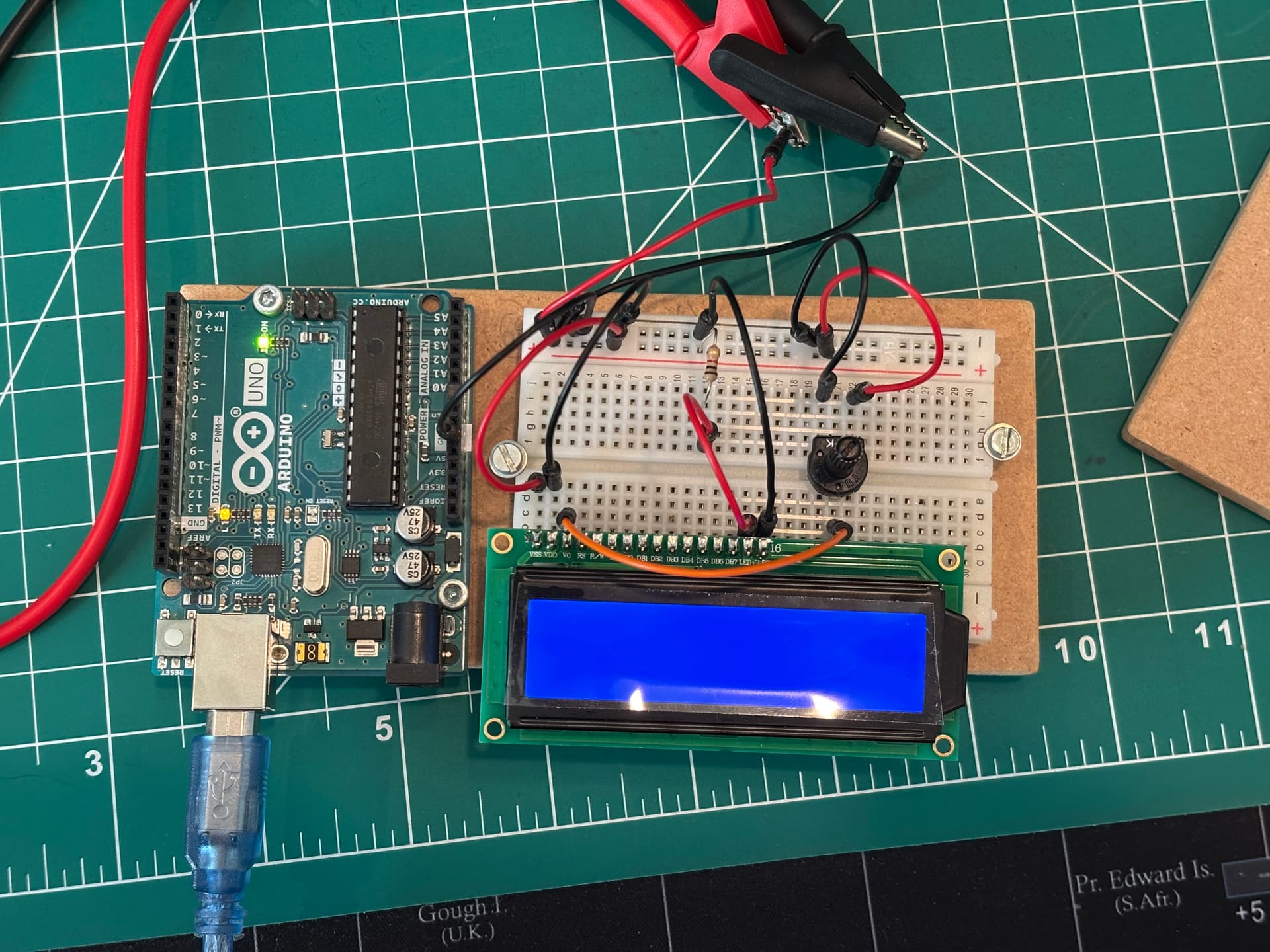
When powering my LCD screen, it displays letters if I have it connected to the Arduino's 5V and GND, but when I connect it to an external 5V supply then even if my grounds are connected, it won't display letters. It will power up, but not display letters. Can someone please help me? Thank you!
I took everything else off and the same thing happened. From the battery 5V it wouldn't display letters, but when I connected it to the Arduino's 5V it displayed letters. I double checked wiring from multiple YT videos and also other forum posts as well and still the same issue.
I also wired it in real life and the same issue happens. Except if I try to power the LCD through the Arduino, the Arduino's lights slowly fade and then it turns completely off.
Here is the schematic that I followed. The only difference between the previous picture and the schematic is that I have disconnected everything except the first 3 pins (VSS, VDD, V0) and last 2 pins (LED+, LED-). I also have a 5V power supply instead of the 9V in the schematic.
well, one difference between your schematic and your breadboard is that you replaced the 220 ohm LED resistor with a 1Kohm resistor. I'm not sure how much this is affecting the performance, and everything else seems to be okay.
However, if the "LED" pins on the display are to illuminate the backlight, it might be that you actually are getting letters on the display, but you cant see them because there isn't enough light for the liquid crystal to do it's job. Does the datasheet for the display say anything about how much current to provide to the LED pins?
I connected a battery to the Arduino and tried powering the LCD through the Arduino's 5V and GND and it didn't make a difference unfortunately.
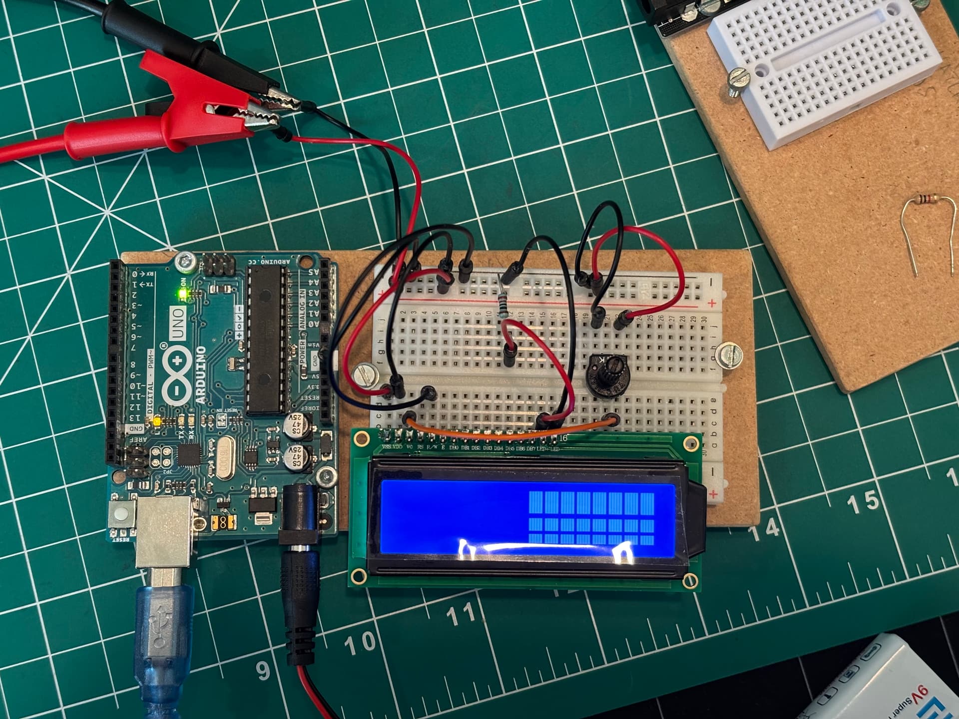
I also double checked that everything was connected properly and now I can adjust the contrast on the right half of the LCD. I have also tried to see if I can display letters on that side by connecting the rest of the pins (RS, E, DB4, DB5, DB6, DB7 to the Arduino, and R/W to GND), and it did not display letters, it just kept the same white blocks.
I switched out the resistor for the 220 Ohm one and it made the screen brighter, maybe that helps.
Unfortunately I couldn't find the data sheet, but since the white blocks appear as I adjust the potentiometer maybe there is enough current that the LCD should be able to display letters. (is that correct? Or is there no correlation between the two?)
That seems correct to me. Liquid crystal requires a certain amount of light behind it in order to work correctly. The 'white blocks' are really little bits of liquid crystal that block the light behind them or allow the light behind them to pass through. If there wasn't enough light behind it to begin with then the LC is doing its job, you just can't see it. By reducing the value of that LED resistor, you are allowing more light behind the LC, so now you can see it working. The potentiometer is a contrast control that allows you to adjust the amount of light behind the LC. Your 220 ohm resistor sets the maximum amount of light, then your potentiometer adjusts it from its minimum to its maximum. You can probably get rid of the potentiometer all together and run a wire from V0 to +5V, which would set the backlight to its maximum value.
Still not sure why only half of your display is working though. Your wiring looks okay to me. Those alligator clips are a little close together for my taste, but your 5V regulator likely has a short circuit protection in it, so not a big deal. At this point, I would recommend checking your code once more to make sure everything is working like you expect it to. Hope this helps!
I checked my code and it should be right. The pins match up, and the program itself is just the "Hello World!" with the counter below it that I copy and pasted so it shouldn't have any problems. I'll see if I can get my hands on another LCD later today in case this one has some sort of issue with only half of it lighting up.
Sometimes copy/paste works for these LCD screens, but sometimes it doesn't. Some of these LCD screens are slightly different from others, so code written for one particular model might not work on every model. Also, I see that your schematic doesn't include connections for DB0-DB3, and I'm guessing that may be the first half of your screen.
If you post your code here, there may be someone who can point out a problem. Be sure to use the CODE tags though.
Right now I'm using a plug that gives 5V DC from the wall. That comes from the alligator clips. Is that sufficient? From my limited understanding the same 5V goes to each component this way and the plug can handle a lot of current so it doesn't really matter as much how much current each device requires. Is that right?
I removed every wire except VCC, VDD, LED+, LED-. The screen is completely blue, there is no white at all.
Here is my code. Since only the right side was working , I tried to print stuff on the right side of it with no success. The blank white rectangles remained. I adjusted the potentiometer a few times as well to see if anything appears, but no text showed up.
In that case, the code is probably good. I agree with @xfpd that something doesn't look great about this display though. Especially that horizontal line through the second row.
Try connecting your RS and EN pins pins to the Arduino (so that they aren't floating) and see if that makes it display correctly.
Also, your 5V "wall wort" should be fine. It probably says on the plug how much output current it is capable of putting out, but chances are good that it is plenty. Motors are the one component that usually draw a lot of current.
I connected those DB0-DB3 but I didn't notice any changes. The left half is still blank. I'll try to find another LCD screen and see if that one works.