So my project is about monitoring the aquarium temperature with DS18B20 temp sensor and switching relay plus leds, based and temperature set points.
There is a transistor on the led and also on the relay. on the relay i also placed a capacitor and diode as other topics explain that the switching relays can scramble the LCD.
Now the switching of relay goes smooth without any problem, what causes the scrambling now is when i switch on the aquarium filter.
I made a power distribution board with a breaker for every user; filter, lightning, heater and Arduino 5v power supply. Switching on another breaker causes change in the power supply to the Arduino which results in the scrambling of the LCD.
What can solve this problem? Would a capacitor on the incoming 5v supply help?
Im not a expert in electronics and i get all solutions from experts online
Thomassen85:
There is a transistor on the led and also on the relay. on the relay I also placed a capacitor and diode as other topics explain that the switching relays can scramble the LCD.
That diagram is not overly helpful and I am not at all sure what the capacitor is supposed to do!
The suggestion is that you place a 100 µF capacitor directly across pins 1 and 2 of the LCD display.
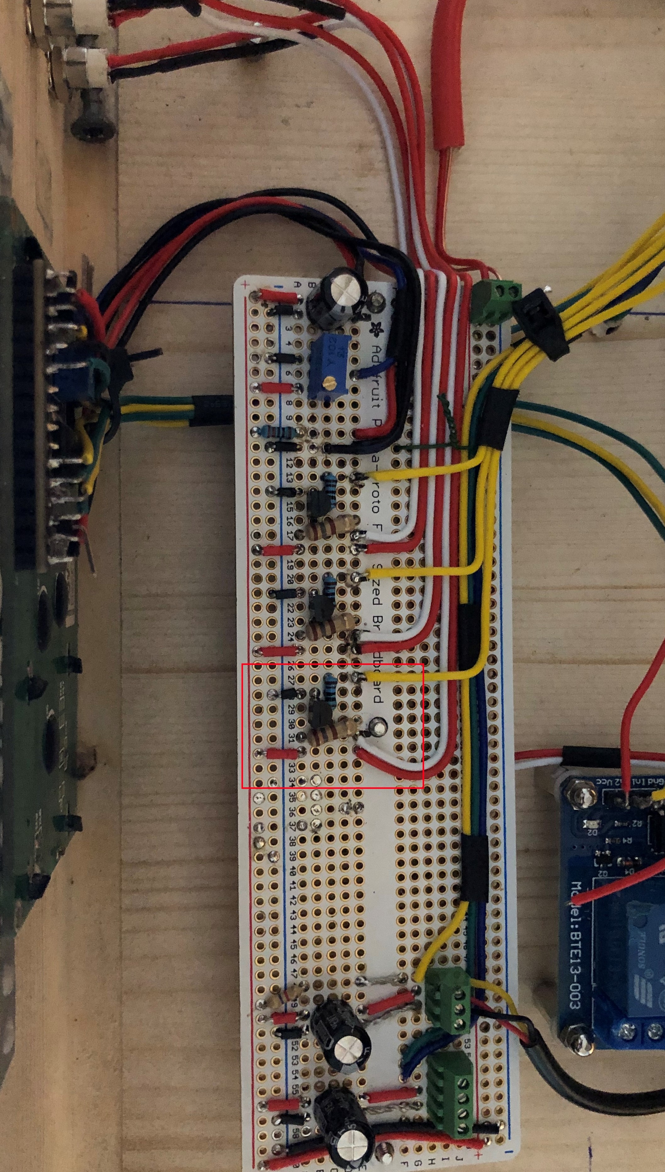
This problem has a lot to do with "wiring dress" - how you run the wires to the Arduino. You may note my advice on this in other posts. A photo of your wiring may be helpful to critique.
Im aware of wires running straight next to each other can cause issues but how i wired it, it should not cause that problem right?
What i should tell is that the 5V 10A power supply was bought from AliExpress so maybe its not that reliable.
Would it help if i place a ferrite bead on the power cable going in the 5v power supply?
And why place a capacitor across pin 1 and 2 of the display? Why not place a capacitor on the incoming 5V wires on the breadboard (the 2 on the bottom of the breadboard on the pic)?
Also good to know that the aquarium filter has a rotor so that might influence more than lets say the lightning or heating that would be switched on at certain moments.
Tested it but it still scrambles when switching on other breakers. Also the temperature sensor goes crazy.
I placed a capacitor on the 5v on the breadboard and a ferrite ring on the power cable to the 5v power supply.
Maybe it would help if i just put a plug on the PSU cable and plug it in the wall socket so its not in the power distribution box next to the others. Not what i want in the end but if that takes away the issue...
I trust that you are not suggesting that could be a finished product? Breadboards are for temporary prototyping and absolutely impractical as a final product.
You might find that EMI issues disappear once you build it onto a PCB or stripboard too, all those long wire links can be acting as inductive loops and aerials for all the rubbish being generated by switching.
AJLElectronics:
You might find that EMI issues disappear once you build it onto a PCB or stripboard too, all those long wire links can be acting as inductive loops and aerials for all the rubbish being generated by switching.
Yes, that is what I was explaining in #2.
Thomassen85:
I'm aware of wires running straight next to each other can cause issues but how i wired it, it should not cause that problem right?
Dead wrong! The problem is that wires not running straight next to each other can and frequently does issues. "Wiring dress" as I referred and explain so often here, means bundling together all the wires that connect one part of the assembly with another.
Now to be fair, it is possible to get "cross-talk" by mostly capacitive coupling if wires are together, which means to say that it is critical that the wires switched by the relays are kept as far as possible from the logic wiring, and that the output wires from the Arduino to the relay module are kept away from all the inputs to the Arduino. But grouping signal or control wires together with their matching ground - and supply - wires, also shields the electrostatic field (that is, capacitive coupling) and minimises that problem.
As AJLElectronics points out, long looping connections provide inductive coupling from or to that part of the circuit and when heavy currents are involved - as happens here - then that is the predominant form of interference. Inductance is proportional to the size (diameter) of the loop so keeping connections short and again, keeping the sides of every such loop together - the signal and the ground travelling as a pair - minimises that loop and is critical to preventing such interference.
It is pretty evident that this is the substantial problem here.
AJLElectronics:
I trust that you are not suggesting that could be a finished product? Breadboards are for temporary prototyping and absolutely impractical as a final product.
You might find that EMI issues disappear once you build it onto a PCB or stripboard too, all those long wire links can be acting as inductive loops and aerials for all the rubbish being generated by switching.
But is this not a pcb i build it on? Its als soldered so that looks pretty permanent to me.
Of course as we now discern, this is not a solderless breadboard so the connections themselves - presuming your soldering is good - are OK.
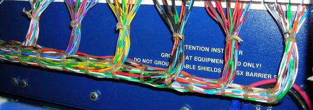
The problem is however the absurdly long and waving, looping connections. The shorter ones should be flat on the circuit board, and the longer ones should be as short as possible and grouped together as I describe and kept more-or-less flat, so that they more resemble the picture I just gave.
Unfortunately, a major re-wire to standard engineering practice is in order.
So i started wiring everything flat on the breadboard and trying to keep all wires sorta bundled. Its almost complete, needs a few more wires and as last i will bundle all wires the best i can.
And BTW just for my learning; what about interference filters and coils, would one help in my situation?
If it would help which one and where to place it? Or do they not do what i think they do?
I am still concerned about that lone wire from the main board to the relay module as it should as previously explained, have a pair. But then I note you appear not to comprehend the relay module. It already includes the driver transistor and opto-isolation so your driver transistor is not needed and only causing more trouble.
Here is how you connect the relay module directly to the Arduino:
Note that the power supply wires must go as a pair to your 5 V power supply while the "IN" and "Vcc" wires (but not ground) go together to your Arduino, separate from the power wires.
So you can see how it works, here is the circuit of the relay module.
Filers are not effective against impulses, and proper wiring is the critical matter here.
Just for reference, here is the eight relay module which may better resemble the connections on the two-relay module you have!
Ok i will have a better look at your post tomorrow. That lone wire you see is only the ground for the relays board and i still need to mount the 5v wire, it got loose around the moment i stopped.
Thomassen85:
That lone wire you see is only the ground for the relays board and i still need to mount the 5v wire, it got loose around the moment I stopped.
I presumed it was one of a pair which would later be mounted. The point is that you do not need (and do not want) the extra transistor you have mounted to control the relay board as the relay board already includes it with additional opto-isolation. The two power wires for the relay go direct from the relay board to the 5 V power supply, separately to other wires - nowhere else - and the control wires go direct to the Arduino and nowhere else!
Today i tested it and for some reason the red led goes on and stays on
The display is working with the correct text and also the temp sensor works correct. When i heat up the temp sensor to the point the red led normally should come on, the text on the display turns jibberish.
At this moment i cant see what is the issue with the red led circuit.
Btw the relays i have not connected yet and if i disconnect the arduino the red led also stays on.
The wires from the breadboard to the arduino i still have to straighten but first all needs to work.