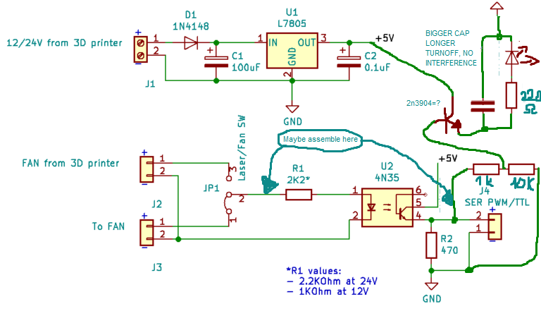
This is a PWM/TTL laser adapter for an Ender 3 pro. with 24v Mainboard 1.1.4v.
Both of these circuits grounds are connected only to each other and both +5v are connected similarly.
"Fan from 3D printer is 24v pwm"
"To laser is TTL 5v"
I'm looking to add an LED as an indicator light to this circuit to improve safety on the device.
I would like if the LED would light once the switch at JP1 is switched to provide signal to the laser.
So far every simple modification i've tried would only cause the LED to light during high duty cycles only.
A few things i am unsure on.
-
I have made JP1 as a SPDT On-On switch, Is this a problem as it's meant to be a simple jumperpin setup?
-
Will the LED being connected across R1 to U2 cause the signal to degrade or distort?
-
Would it be smarter to use a second switch or a DPDT On-On and have the LED + resistor take power from the output of the L7805?
The easiest would be to put the LED in series with R2. Measure the voltage drop across R2, and calculate your current. Be sure you have at least 3 volts. If so add led in series and subtract the LED Vf from your reading and calculate new resistor to supply the same current.
"Fan from 3D printer is 24v pwm"
"To laser is TTL 5v"
Neither of these will factor into it?
Hah, you could use an astabile latch that detects pin 4 of the opto, and draws from 5V to light the LED, it would be slightly delayed at turnoff. How small does it need to be?
Maybe a diode that charges a smallish capacitor paralel to the the led with its resistor is enough to keep it bright, watch the current draw as to not fry the opto. If put before R1 increase 220 ohm to value of R1 i guess, and match grounds.
Semtex9:
Hah, you could use an astabile latch that detects pin 4 of the opto, and draws from 5V to light the LED, it would be slightly delayed at turnoff. How small does it need to be?
Maybe a diode that charges a smallish capacitor paralel to the the led with its resistor is enough to keep it bright.
Seems a bit over the top.
Why not an LED and resistor from the left of R1 to GND. Calculate the resistor value to allow about 30mA.
windoze_killa:
Seems a bit over the top.
Why not an LED and resistor from the left of R1 to GND. Calculate the resistor value to allow about 30mA.
because ih has a duty cycle that dims the led regerdless, but he could pull it off I guess just with lowering R1 and putting it just in series, or like you said, no degradation.... LED would flicker along with the opto. this is even more over the top, but should limit any interference to the workings of his circuit, if its still dim smaller cap parallel to the 10K, but thru a diode thats series before 1k, led would not flicker, it increases the led duty cycle in regerds to the laser. If its taken before R1, increase 1k to account for higher voltage, and match grounds
Thanks for the quick replies! I will have a look later on this evening at your posts. Also if any of you have experience with "Inkscape, Jtech Plugin, Gcode > LaserGRBL" I'd love to ask a question or two about homing/Build platform scales.
Solved this myself...
Semtex9:
because it has a duty cycle that dims the led regerdless, but he could pull it off I guess just with lowering R1 and putting it just in series, or like you said, no degradation.... LED would flicker along with the opto.
Thanks for the reply! It seems like i had the right idea avoiding placing the LED on the data line.
this is even more over the top, but should limit any interference to the workings of his circuit, if its still dim smaller cap parallel to the 10K, but thru a diode thats series before 1k, led would not flicker, it increases the led duty cycle in regerds to the laser. If its taken before R1, increase 1k to account for higher voltage, and match grounds.
I like this idea but are you saying it might increase the duty cycle? That would be a negative result if so as i do not want my machine to burn...:o
Mabye i should just buy a DPDT switch to keep the two isolated from each and avoid any unexpected consequences
One final question to add to all this. Is it possible to have two devices measuring a PWM signal and not have them distort it?
I wanted to connect a solenoid air valve to also activate on a high duty cycle. To provide air assist on laser cutting.
Two valves i have found here claim to operate at the following
12V/ Unknown W/ Max = 50PSI
12V/ "about 5W"/ Max = 116PSI
My pressure vessel can hold at max = 40Psi / 2068mmHg
I have some Nanos sitting around the house going unused and was considering using them as a controller for a relay?
Would a simple 12V relay with 5v input signal be able to keep up with the timing of the PWM? I would only need it open when the duty cycle is high (Laser On).
If not what suggestions do you have instead of a relay to operate a 12v/24v solenoid valve? Transistor?
(Also your thoughts on whether air assist is at all needed for a 5.5w laser module.
I do plan on cutting with it. Most of the posts i've read talk about lotsa smoke.)
Thanks again for the help so far its been really usefull.
raschemmel:
pulseIn()
Care to give any info as to why pulseIn could be usefull?
A ProMini sells for about $3.
If you used an arduino, PulseIn() is the arduino function for measuring PWM.
FYI
raschemmel:
A ProMini sells for about $3.
If you used an arduino, PulseIn() is the arduino function for measuring PWM.
FYI
Thanks for the info.
Would you know if a relay would be able to switch fast enough? Talking microsecond intervals
So i'd use the arduino to measure the PWM and then what?
Would something like this be simpler to impliment?
You can't seriously be asking if an electromechanical relay can switch
in the uS ?!
It depends on the relay. But they usually take around 10ms (milliseconds) to switch on, or off. So about 100 flips per second (50 Hz). BUT such "fast" switching rates (for relays), is NOT a good idea.
Google: "typical relay switching time"
I saw something in your post about measuring PWM but nothing about using any arduino to do it.
An ATTiny85 sells for about $1.50. It can be programmed using an arduino UNO.
Should you use an arduino to measure PWM ?
That is a question only you can answer.
I simply think you should be aware of all your options when you make it.
I'm not telling you what to do. I have built dozens of ATTiny85 circuits and dozens of ATMega328 breadboarded
circuits IC with
(Google "ATMega328 with OPIBOOT BOOTLOADER"
and even built my own programmer:
(search the forum for "attiny85 & atmega328 programmer")
to save time.
(Note: the post link function doesn't seem to be working for me right now)
raschemmel:
You can't seriously be asking if an electromechanical relay can switch
in the uS ?!
Google: "typical relay switching time"
I saw something in your post about measuring PWM but nothing about using any arduino to do it.
Thanks again for the reply.
I'll say what i need clearly as i seem to have left everyone a bit confused including myself... 
Components =
- Ender 3D Printer (PSU = -12v to +12v DC) (Controller = ATMEGA1264p)
- Solenoid NC = 12v 3Watt
To do =
- Measure 24v PWM Laser control signal (0-225)
- High measurement = 12v Solenoid Open
- Low Measurement = 12v solenoid closed
"High Measurement" = <16v
"Low Measurement" = >16v
I was not sure what I could use to switch a 12v supply quickly enough. I'm sorry for the questions i've worked with 0-5v pwm but the fact of the -12v to +12v is throwing me off at a tangent.
Best idea so far is this =
Use an Arduino Input to measure the PWM
Have an Arduino Output trigger a suitable transistor to switch the solenoid.
Referring to schematic in your OP (Original Post) , as opposed later posted modified schematics. the first thing
that comes to mind that we need is your initial SITREP (Milspeak for SITUATION REPORT), which I cannot find
anywhere in this thread. It would read like the following:
- I decideded to ______ __________
- I created proposed circuit schematic and list of required parts
3 I ordered required parts
- I breadboarded proposed circuit
OR
- I did some initial bench testing using breadboarded circuits
- I collected data
- Data is as follows: (describe data collected/measurements taken\
- Conclusions made based on testing: (state conclusions)
- Currently possess Arduino(XXXX), and have experience using arduinos
- Have no arduino and no arduino experience
- I have a DMM
12 I have NO DMM
- I have an oscilloscope
- I have no oscilloscope
- I have run some software tests
16 I have not run any tests.
- I have built a circuit
- I don't need to build a circuit because I bought the laser adaptor which is all I need (other than the led,]
Conversely, failing to have completed above steps, you should make the following statement:
"I have done nothing" (aside from posting on the forum to ask what to do)
"I have not ordered anything"
Why am I saying this ?
Do you KNOW what TTL means (yes/no) ?
Do you realize that if you want to maintain isolation, you can simply add an opto coupler to the TTL output,
invert the signal and read it on any arduino digital input ? (invert because the opto will invert the signal)
The pulseIn() function can then be used to measure the PWM on the digital input pin.
The led addition has already been addressed by another poster.
raschemmel:
Referring to schematic in your OP (Original Post) , as opposed later posted modified schematics. the first thing
that comes to mind that we need is your initial SITREP (Milspeak for SITUATION REPORT), which I cannot find
anywhere in this thread. It would read like the following:
Why am I saying this ?
Do you KNOW what TTL means (yes/no) ? Yes in theory but in practice I loose my stepping. Any signal a transistor would output. I loose my stepping when it gets to converting across.
Do you realize that if you want to maintain isolation, you can simply add an opto coupler to the TTL output,
invert the signal and read it on any arduino digital input ? (invert because the opto will invert the signal)
(Would this in anyway damage the signal if it is being shared with something else? IE Laser Adapter Board
Or because the adapter board uses an opto to isolate, does that mean all will be good?)
The pulseIn() function can then be used to measure the PWM on the digital input pin.
The led addition has already been addressed by another poster. It has, I do appreciate the continued support.
- I decideded to put a laser on my Ender 3 3D printer. I have a 5.5w laser cutter head with external power and 0-5v pwm control.
- I copied SID's circuit schematic for Translating/Shifting the signal and have it working as needed.
(This takes the 24V fan output and converts it to a readable voltage for the laser 0-5v)
- I then decideded to add "Air Assist" for increasing cutting depth/Laser efficiency (Less Smoke = More Cut)
- I now need to translate the same signal from the Printer to the Solenoid.
- I have 2 x solenoids available sitting in a draw. (12v 3w / 24v 4.8w)
- I did not do some initial bench testing using breadboarded circuits.
- Data is as follows:
My results where non conclusive as my cheap Bench PSU maxs @15v but i have found that using a transistor to switch the voltage would be quicker than a box relay. I also tested both solenoid and they work as intended
- Conclusions made based on testing:
24v PWM Fan signal -> Shift to 5v -> InputPin AnalogRead -> OutputPin DigitalWrite -> Transistor "5v". -> +12v supply
(24v PWM Fan Signal -> Shift to 5v -> Transistor "3.3v Saturation?" -> +12v Supply)
(24v PWM Fan Signal -> Transistor "16v Saturation?" -> +12v Supply)
I would need to check the signal voltage to ensure it's either "0v / 24v signal" OR "-12v / 12v" That will get me a better idea of how to do this. How would i do this with with a cheap DMM?
- I Currently possess Arduino(Mega,Nano,Teensy,Tiny,EnderControl Board), and have decent enough experience using arduinos
"Clearly it doesn't show"
- I have a DMM.
- I have no oscilloscope
- I have run some software tests - "Falstad Used previously but unsuitable to do anything with microcontrollers"
- I now need to build a circuit to take the laser control signal and have it open a solenoid when 100%.
(24v PWM Fan Signal -> Transistor "16v Saturation?" -> +12v Supply)
I am looking at this being the prime solution as long as the Fan signal is 0-24v. If it is not then i am back to scratching scalp.
TTL ?
do ou know what that means ?
raschemmel:
TTL ?
do ou know what that means ?
My god. Literally just got to sleep and woke up sudden after realising my dumb ****ery.
Thanks for helping me find the right question.
Will.post resolution tomorrow.
raschemmel:
TTL ?
do ou know what that means ?
Transistor Transistor Logic. I've allowed myself to be confused into thinking this is about converting PWM to TTL when all i need is to step the voltage down, add the signal to the new voltage and increase current potential of the output.
Testing the solenoid gives me (Unable to read any stable resistance?)
Partly Open = 9v @ 200mA
Fully Open = 10v to 12v @ 250mA
Fully Closed = 1.5v @ 50mA
This tells me that a 2N35 optocouple will no be able to handle the current so i will need to find a suitable replacement.
I cannot find any optocouplers that will handle a load of more than 80mA... Should i have the opto feed
(Any usefull seach querys or websites would be appreciated. I use farnell as they are a local supplier)
I've put any readings i've made in the image below.
I've re-drawn the original circuit to include the seperate 12v regulated voltage and optocoupler
I will probably replace the blue highlighted subcircuit with something that will switch the 12v supply on at "100%/24v" and off at "=>99%/23.5v" This is why i was thinking of using a transistor as a switch because they can handle higher current loads but are not isolated like an optocoupler.... but now i feel i've gone full circle.... Ahhhh...!!!
Do you have any good circuit simulators that will have librarys of L78 voltage regulators to test with?
I'm sorry but I don't see any definitive indication
that you yet understand that TTL is the electronics
official name for 5V LOGIC !
Yes, I mean the SAME 5V logic used on ALL arduino
pins , Including ANALOG pins UNLESS they are
being used for analog input;
Google:
"arduino can analog pins be used as digital"
This of course means that the laser output labeled
TTL is an arduin compatible logic signal , albeit
one that is isolated by an optocoupler, which is why
I said if you want to maintain that isolation you
would need another optocoupler and then you would need to use an INVERT function because
optos invert the signal. (that is if you want to
use the pukseIn() function to neasure the PWM)
Switching at 23.5V would require a comparator
"Threshold Detector" (Google it)
RE: SOLENOID
For starters the solenoid should connected from 12V to the collector of the opto but if since it draws more
current than the opto can source , you should probably use a mosfet or darlington transistor and turn that
on with the opto coupler.
Google :'driving solenoid with opto and mosfet'
"https://www.google.com/search?q=driving+solenoid+with+optocoupler+and+mosfet&client=firefox-b-1-d&tbm=isch&source=iu&ictx=1&fir=rfKYyW5BISt7UM%252Cw8l1XWDU4Xc2NM%252C_&vet=1&usg=AI4_-kQC97LU-Yexb4NJ2Xl0b3Hg67HzKA&sa=X&ved=2ahUKEwiQpqmyzq_sAhUHgp4KHTZ4DooQ9QF6BAgKEEc#imgrc=rfKYyW5BISt7UM"
Since it is a TTL signal it probably makes more sense to route the signal to an arduino digital
input on the TTL side instead of the isolated
side after the opto.
You would have to splice into the cables that
plug into the laser adaptor at the fan plug side,
at J2-pin-1, before JP1, rather than from U2-pin-4.
You would need the
J2-pin-2 return to connect to the arduino GND
unless that's where it is already coming from
because your schematic doesn't include arduino
connections.