LM358 50Hz 5V sine wave?

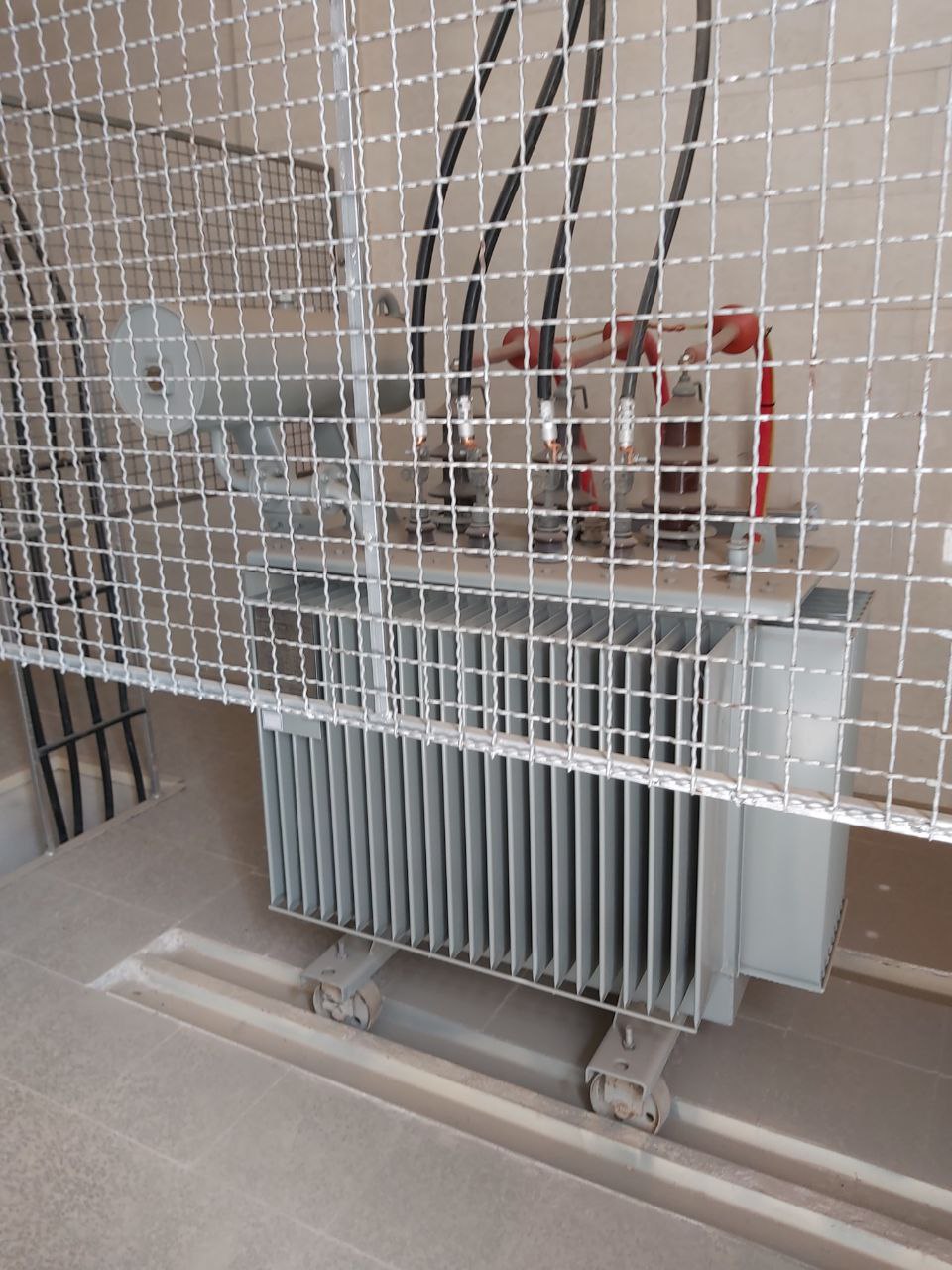
This task is a job for a professional electrician, they have all the equipment to identify phases and they are qaulified to do it safely as well as provide a wealth of advice that you probably need...

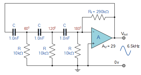
The idea of using an opamp oscillator was flawed from the start as it would be too imprecise and drift all over the place. Using a quartz clocked device to compare zero-crossings might have been a viable approach, but you still have to be aware than mains frequency changes over time (within limits), so that absolute phase information has a very limited lifetime unless you compare simultaneously (say over a wireless network).

1 Like

Or better, synchronize to GPS time.

1 Like

I have worked on the wireless network for this project before, but it was not possible because of the long delay of the wireless network

He's not necessarily talking about WiFi.

You can register time reference stamps using GPS locked time, and compare over the net.

Indeed a fixed low latency link is needed, but simple ISM transceivers can give you that is a reasonably small packet size and high baud rate chosen.

But anything involving 3-phase mains call in the experts, they know their stuff and can probably just tell you all you need to know.

1 Like

That does give me pause - large scale industrial/residential power distribution is not for hobbyists.

1 Like

Check this
https://www.youtube.com/watch?v=GMbN9nb3qyk

1 Like

No it's 63Kv power line. I worked with 220 volts :smiley:

Professionally? Are you a certified electrician or electrical engineer?

All of which still turns out to be entirely irrelevant to the actual problem. :face_with_raised_eyebrow:

I'll try for #100. :sunglasses:

BTW with 50 Hz one cycle is 20 ms, 120° is then about 6 ms, you must stay within +/- 3 ms of the reference frequency to reliably determine phase. Even if the mains frequency were absolutely stable and you had a very good 3 ppm oscillator the phase information is lost after 1000 second - less than 20 minutes!

1 Like

Guys, what do you think about phase shift RC Oscillator circuit ? like this:

RC-Oscillator-Op-amp-Circuit.png

Well it is an oscillator, but apart from that it will give you a different reading each time you turn it on. It will not be accurate, and it will drift with time and temperature.

1 Like

It's the exact same concept i showed you earlier but not yet dimensioned for 50Hz.

Let's face it, you're not really going anywhere with this. Plesse just do what the others have said and get a qualified electrician to get this job done.

Why do you keep on talking about phase shifts and oscillators? :face_with_raised_eyebrow:

You have not so far explained any requirement whatsoever for measuring phase.

Hi,
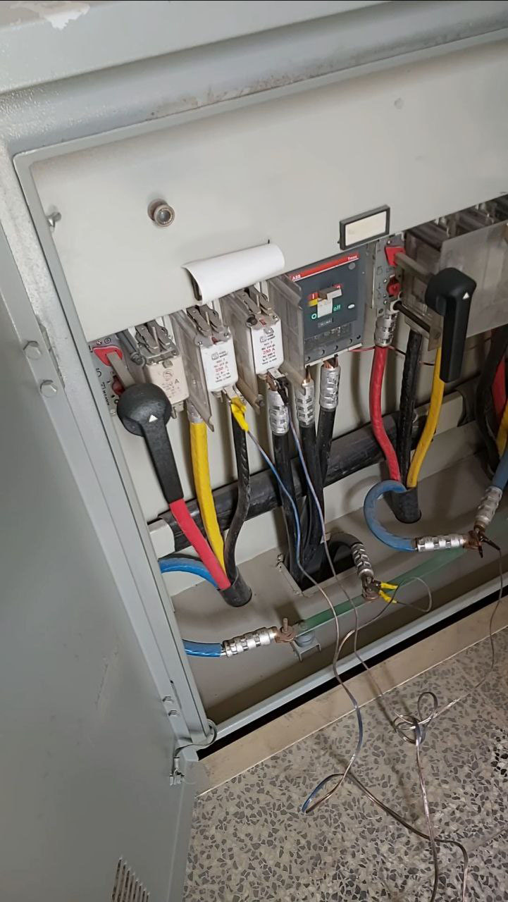
If you are just trying to balance three phase power, all you need to do is measure the load, that is the voltage and current between phases.
How do you expect to do this by comparing phase angles.

PLEASE.. PLEASE.. do some research in to power systems and 3 phase characteristics.

Can you please tell us your experience and or qualifications, if any, in high voltage power systems?
What is your location, country?

Thanks.. Tom... :smiley: :+1: :coffee: :australia:

So, I built my own oscillator and tested it with AC power and found an approximate ~200 degree angle between the oscillator and AC power.

You have alligator clips and speaker wire connected to a multi KW transformer. That says it all.

Hi,
That trace has period of 14.2ms and a frequency of 70.7Hz, read the scope.
How can you get anywhere near a stable phase difference with 50Hz.

How did you connect and measure these results?
Can you post a schematic please?

What is your code?

Thanks.. Tom... :smiley: :+1: :coffee: :australia: