I'm working with an Arduino Giga, and I am working on a system to measure flow and pressure from a peristaltic pump. When I get the Arduino to measure the signal from the sensors, it often reads low, and I don't know why. This post is a bit long, but I wanted to make sure that I provide enough information. I am getting similar low readings from both the flow and pressure sensor, but I have focused more on the flow sensor in trying to troubleshoot, and it's also a shorter post if I talk about just one of the sensors. This is my first major Arduino project and first electronics project, and it's pretty ambitious, so forgive me if things might be a bit off with some of my setup.
In my system, I have a peristaltic pump that outputs to a bubble trap made from a 100 ml syringe with ~100 ml of air and then about 1.5 ft/45 cm of compliant silicone tubing to help reduce the force of the pulsations from the peristaltic pump. It doesn't completely remove the pulsations, so I implemented an exponential moving average (EMA) and a Kalman filter to try to clean up the signal to get an average that would still be reasonably responsive. After the silicone tubing, I have my flow sensor then my pressure sensor. I am using an Renesas FS1203-DL flow sensor (I am using the voltage rather than the I2C for simplicity) and a generic industrial pressure sensor.
The setup that I am currently testing is part of a larger system, and I am trying to calibrate the sensors. The pressure and flow sensors are both 5V, and I have a 10µF electrolytic and a 0.1µF ceramic capacitor bridging the power leads going to the sensor (and also a 1000µF capacitor coming out of the 5V buck converter that is feeding all of the 5V components of the larger system). For the flow sensor, I use a combination of a 6.2kΩ resistor and a 12kΩ resistor to create a voltage divider to drop the signal to be within the 3.3V of the Arduino Giga (I don't drop the pressure signal with a voltage divider as it's a 5 psi sensor and my system doesn't seem to be able to generate more than about 3 psi). To help clean up the signal, I also added an RC low-pass filter with a 1kΩ resistor from and a 0.1µF ceramic capacitor to ground. I'm using 12-bit resolution (0-4095).
Before I had implemented the RC low-pass filter, this is the output that I was getting if I logged the data every 10 ms (though this really slowed down the pump due to consuming so much processing time, so I can't accurately say what the time intervals actually are, and the pump would occasionally stop and start that would cause spikes in the flow and pressure). The dark blue dots are the raw analogue data, the orange is the raw signal fed through a Kalman filter algorithm, and the green is an EMA (alpha = 0.02) that is also fed through a Kalman filter. The idea is that I can use the EMA to adjust the speed of the pump to target a programmed flow and/or pressure rate.

I am trying to calibrate the sensors to the flow that I am seeing so that I can create an equation to match the readings to a flow output. I was in the process of starting this and was getting flow sensor readings that were a bit high (using a multimeter, I was getting signals of about 0.5V but ADC of 600-700). I implemented the RC low-pass filter and I was getting about 0.45V on a multimeter and ADC readings of ~500-550, which was expected (though it was still a bit high for the expected 0.33V for zero flow from the sensor, which should be about 400 in ADC). I was able to get fairly consistent values, then suddenly sensor readings went back up to 600-700. I played around, I switched analogue pins, and I replaced a trimpot with a voltage divider (I tested the resistors, I and I think they were 6.12kΩ and 11.90kΩ, which would give me 3.302V from 5V, if memory serves) and I started getting signals of ~550 again. Then all of a sudden I started getting readings of 250-400, even though the multimeter was still showing 0.45V. Now, sometimes I will get readings of ~500-550, but more often I am getting 250-400, and I haven't been able to find a pattern.
I tried a few different things. I though that maybe the sensor needed time to warm up, but letting the system run for several minutes seemed to make no difference. I connected the sensor signal wire to either ground or 5V (through the voltage divider and RC low-pass filter), let the system run for 5 min to make sure that I was getting a stable EMA and Kalman filtered signal (though the raw average and range were reset every second), and these were the results:
Connected to sensor (not flow):
•EMA: 297.66
•filtered EMA: 296.99
•filtered raw data: 264.90
•average: 309.42
•range: 0 - 639
Connected to ground:
•EMA = 1.89
•filtered EMA = 1.74
•filtered raw data = 1.74
•average = 1.00
•range = 0–202
Connected to 5V:
•EMA = 3984.29
•filtered EMA = 3986.80
•filtered raw data = 3968.63
•average = 4005.91
•range = 3712–4095
I am more or less getting the readings that I expect from both ground and 5V, but I am getting low readings from the sensors. Does anyone has any idea why I am getting low readings from my sensors?
Here is the code that I am using (though I've left out the part of initializing the USB and data logging code). To explain the code:
-Get an initial sensor reading at the startup and show it on the serial monitor (it reads quite low at this point)
-Cycle the stepper motor and pump for 2000 steps to flush any water that is in the sensor
-Let the system settle for 10 seconds to allow the flow to fully stop
-Establish a baseline EMA and show it on the serial monitor
-Continue to collect and process signal data from the flow and pressure sensors every 10 ms, log the data every second, and display the information every 10 seconds on the serial monitor
#include <AccelStepper.h>

// USB mass storage device libraries
#include <Arduino_USBHostMbed5.h> // v0.3.1
#include <DigitalOut.h>
#include <FATFileSystem.h>

#include <stdio.h>

#include "kalman.h"

// Define stepper interface type and pins
int motorInterfaceType = 1;
int stepPin = 43;
int dirPin = 41;

AccelStepper pumpMotor(motorInterfaceType, stepPin, dirPin);

USBHostMSD msd;
mbed::FATFileSystem usb("usb");
int err;

// Initialize filters with guessed tuning values (tune as needed)
KalmanFilter kalmanFlowZero(0.01, 0.3, 1.0, 0.0);     // For flowRateEMAzero
KalmanFilter kalmanPressureZero(0.01, 0.3, 1.0, 0.0); // For pressureEMAzero
KalmanFilter kalmanFlow(0.01, 0.3, 1.0, 0.0);         // For flowEMA
KalmanFilter kalmanPressure(0.01, 0.3, 1.0, 0.0);     // For pressureEMA
KalmanFilter kalmanMeanFlow(0.01, 0.3, 1.0, 0.0);     // For meanFlowReadings
KalmanFilter kalmanMeanPressure(0.01, 0.3, 1.0, 0.0); // For meanPressureReadings

float alpha = 0.02;

char filename[] = {"/usb/log-15.csv"};
unsigned long readingsTaken = 0;
float testSpeed = 0.0;

const float maxTestSpeed = 1700.0; // Practical upper limit
const unsigned long testDuration = 1800000; // 30 minutes

float flowRateEMAzero = 0.0;
float pressureEMAzero = 0.0;
float filteredFlowRateEMAzero = 0.0;
float filteredPressureEMAzero = 0.0;
float flowEMA = 0.0;
float pressureEMA = 0.0;
float filteredFlowEMA = 0.0;
float filteredPressureEMA = 0.0;

int testStart = 0;
int serialTime = 0;

int analogFlow = 0;
int analogPressure = 0;
float sensorSumFlowReadings = 0.0;
float sensorSumPressureReadings = 0.0;
int minAnalogFlow = 4095;
int maxAnalogFlow = 0;
int minAnalogPressure = 4095;
int maxAnalogPressure = 0;
float meanFlowReadings = 0.0;
float meanPressureReadings = 0.0;
float filteredPressure = 0.0;
float filteredFlow = 0.0;

//Setting pin for flow sensor data
const int flowSensorPin = A2;

// Setting pins for pressure sensor data
const int pressureSensorPin = A1;

// Setting pin for speaker
const int speaker = 8;


void setup() {
  Serial.begin(115200);
  while (!Serial);

  //Enable the USB-A port
  pinMode(PA_15, OUTPUT);
  digitalWrite(PA_15, HIGH);

  // Create speaker for alarms
  pinMode(speaker, OUTPUT);
  digitalWrite(speaker, LOW);

  analogReadResolution(12);

  initializeUSB();

  tone(speaker, 750, 250);

  testStart = millis();
  unsigned long currentTime = millis();
  while (millis() - currentTime < 1000) {

    readingsTaken++;

    analogFlow = analogRead(flowSensorPin);
    flowRateEMAzero = alpha * (float)analogFlow + (1.0 - alpha) * flowRateEMAzero;
    filteredFlowRateEMAzero = alpha * (float)analogFlow + (1.0 - alpha) * filteredFlowRateEMAzero;
    filteredFlowRateEMAzero = kalmanFlowZero.update(filteredFlowRateEMAzero);
    filteredFlow = kalmanMeanFlow.update(analogFlow);
    minAnalogFlow = min(minAnalogFlow, analogFlow);
    maxAnalogFlow = max(maxAnalogFlow, analogFlow);
    sensorSumFlowReadings += analogFlow;

    analogPressure = analogRead(pressureSensorPin);
    pressureEMAzero = alpha * (float)analogPressure + (1.0 - alpha) * pressureEMAzero;
    filteredPressureEMAzero = alpha * (float)analogPressure + (1.0 - alpha) * filteredPressureEMAzero;
    filteredPressureEMAzero = kalmanPressureZero.update(filteredPressureEMAzero);
    filteredPressure = kalmanMeanPressure.update(analogPressure);
    minAnalogPressure = min(minAnalogPressure, analogPressure);
    maxAnalogPressure = max(maxAnalogPressure, analogPressure);
    sensorSumPressureReadings += analogPressure;

    delay(10); // Small delay for stable readings

  }

  write_log_entry();

  Serial.print("\n*****Calibration run @ ");
  Serial.println(millis() / 1000);
  Serial.println(" in 12-bit resolution*****");
  Serial.print("Initial ananlogue flow readings: ");
  Serial.print("\t• flowRateEMAzero: ");
  Serial.println(flowRateEMAzero);
  Serial.print("\t• filteredFlowRateEMAzero: ");
  Serial.println(filteredFlowRateEMAzero);
  Serial.print("\t• filteredFlow: ");
  Serial.println(filteredFlow);
  Serial.print("\t• Average flow: ");
  Serial.println(sensorSumFlowReadings / readingsTaken);
  Serial.print("\t• Analogue flow ADC range: ");
  Serial.print(minAnalogFlow);
  Serial.print(" - ");
  Serial.println(maxAnalogFlow);
  Serial.println();

  Serial.println("Initial ananlogue pressure readings: ");
  Serial.print("\t• pressureEMAzero: ");
  Serial.println(pressureEMAzero);
  Serial.print("\t• filteredPressureEMAzero: ");
  Serial.println(filteredPressureEMAzero);
  Serial.print("\t• filteredPressure: ");
  Serial.println(filteredPressure);
  Serial.print("\t• Average pressure: ");
  Serial.println(sensorSumPressureReadings / readingsTaken);
  Serial.print("\t• Analogue pressure ADC range: ");
  Serial.print(minAnalogPressure);
  Serial.print(" - ");
  Serial.println(maxAnalogPressure);
  Serial.println();

  pumpMotor.setMinPulseWidth(2);
  pumpMotor.setAcceleration(100);  //
  pumpMotor.setMaxSpeed(maxTestSpeed);

  pumpMotor.setCurrentPosition(0);
  pumpMotor.moveTo(2000);
  while (pumpMotor.distanceToGo() != 0) {
    pumpMotor.run();  // Non-blocking movement
  }

  minAnalogFlow = 4095;
  maxAnalogFlow = 0;
  minAnalogPressure = 4095;
  maxAnalogPressure = 0;
  readingsTaken = 0;
  sensorSumFlowReadings = 0;
  sensorSumPressureReadings = 0;

  currentTime = millis();
  serialTime = millis();
  Serial.print("\nLetting flow readings settle");
  while(millis() - currentTime <= 15000){
    if(millis() - serialTime >= 500){
      Serial.print(".");
      serialTime = millis();
    }
  }

  Serial.print("\nSetting EMA zero");

  currentTime = millis();
  serialTime = millis();
  while (millis() - currentTime < 10000) {

    readingsTaken++;

    analogFlow = analogRead(flowSensorPin);
    flowRateEMAzero = alpha * (float)analogFlow + (1.0 - alpha) * flowRateEMAzero;
    filteredFlowRateEMAzero = alpha * (float)analogFlow + (1.0 - alpha) * filteredFlowRateEMAzero;
    filteredFlowRateEMAzero = kalmanFlowZero.update(filteredFlowRateEMAzero);
    filteredFlow = kalmanMeanFlow.update(analogFlow);
    minAnalogFlow = min(minAnalogFlow, analogFlow);
    maxAnalogFlow = max(maxAnalogFlow, analogFlow);
    sensorSumFlowReadings += analogFlow;

    analogPressure = analogRead(pressureSensorPin);
    pressureEMAzero = alpha * (float)analogPressure + (1.0 - alpha) * pressureEMAzero;
    filteredPressureEMAzero = alpha * (float)analogPressure + (1.0 - alpha) * filteredPressureEMAzero;
    filteredPressureEMAzero = kalmanPressureZero.update(filteredPressureEMAzero);
    filteredPressure = kalmanMeanPressure.update(analogPressure);
    minAnalogPressure = min(minAnalogPressure, analogPressure);
    maxAnalogPressure = max(maxAnalogPressure, analogPressure);
    sensorSumPressureReadings += analogPressure;

    delay(10); // Small delay for stable readings

    if(millis() - serialTime >= 500){
      Serial.print(".");
      serialTime = millis();
    }
  }

  write_log_entry();

  Serial.print("\n*****Calibration run @ ");
  Serial.print(millis() / 1000);
  Serial.println(" in 12-bit resolution*****");
  Serial.print("Start ananlogue flow readings: ");
  Serial.print("\t• flowRateEMAzero: ");
  Serial.println(flowRateEMAzero);
  Serial.print("\t• filteredFlowRateEMAzero: ");
  Serial.println(filteredFlowRateEMAzero);
  Serial.print("\t• filteredFlow: ");
  Serial.println(filteredFlow);
  Serial.print("\t• Average flow: ");
  Serial.println(sensorSumFlowReadings / readingsTaken);
  Serial.print("\t• Analogue flow ADC range: ");
  Serial.print(minAnalogFlow);
  Serial.print(" - ");
  Serial.println(maxAnalogFlow);
  Serial.println();

  Serial.print("Start ananlogue pressure readings: ");
  Serial.print("\t• pressureEMAzero: ");
  Serial.println(pressureEMAzero);
  Serial.print("\t• filteredPressureEMAzero: ");
  Serial.println(filteredPressureEMAzero);
  Serial.print("\t• filteredPressure: ");
  Serial.println(filteredPressure);
  Serial.print("\t• Average pressure: ");
  Serial.println(sensorSumPressureReadings / readingsTaken);
  Serial.print("\t• Analogue pressure ADC range: ");
  Serial.print(minAnalogPressure);
  Serial.print(" - ");
  Serial.println(maxAnalogPressure);
  Serial.println();

  minAnalogFlow = 4095;
  maxAnalogFlow = 0;
  minAnalogPressure = 4095;
  maxAnalogPressure = 0;
  readingsTaken = 0;
  sensorSumFlowReadings = 0;
  sensorSumPressureReadings = 0;
}

void loop() {

  flowEMA = 0.0;
  pressureEMA = 0.0;
  filteredFlow = 0.0;
  filteredPressure = 0.0;
  minAnalogFlow = 4095;
  maxAnalogFlow = 0;
  minAnalogPressure = 4095;
  maxAnalogPressure = 0;
  int readingTime = millis();
  bool startUp = true;
  int logTime  = millis();

  Serial.print("\nSetting EMA baseline");

  while(millis() - testStart <= testDuration) {

    if(millis() - readingTime >= 10){
      readingsTaken++;

      analogFlow = analogRead(flowSensorPin);
      flowEMA = alpha * (float)analogFlow + (1.0 - alpha) * flowEMA;
      filteredFlowEMA =  alpha * (float)analogFlow + (1.0 - alpha) * filteredFlowEMA ;
      filteredFlowEMA  = kalmanFlow.update(filteredFlowEMA );
      filteredFlow = kalmanMeanFlow.update(analogFlow);
      maxAnalogFlow = max(maxAnalogFlow, analogFlow);
      minAnalogFlow = min(minAnalogFlow, analogFlow);

      analogPressure = analogRead(pressureSensorPin);
      pressureEMA = alpha * (float)analogPressure + (1.0 - alpha) * pressureEMA;
      filteredPressureEMA = alpha * (float)analogPressure + (1.0 - alpha) * filteredPressureEMA;
      filteredPressureEMA = kalmanPressure.update(filteredPressureEMA);
      filteredPressure = kalmanMeanPressure.update(analogPressure);
      maxAnalogPressure = max(maxAnalogPressure, analogPressure);
      minAnalogPressure = min(minAnalogPressure, analogPressure);

      sensorSumFlowReadings += analogFlow;
      sensorSumPressureReadings += filteredPressure;

      if (millis() - serialTime >= 10000 && millis() % 10000 >= 10){

        Serial.print("\n*****Calibration run @ ");
        Serial.print(millis() / 1000);
        Serial.println(" in 12-bit resolution*****");

        Serial.print("Ananlogue flow readings: ");
        Serial.print("\t• flowEMA: ");
        Serial.println(flowEMA);
        Serial.print("\t• filteredFlowEMA: ");
        Serial.println(filteredFlowEMA);
        Serial.print("\t• filteredFlow: ");
        Serial.println(filteredFlow);
        Serial.print("\t• Average flow: ");
        Serial.println(sensorSumFlowReadings / readingsTaken);
        Serial.print("\t• Analogue flow ADC range: ");
        Serial.print(minAnalogFlow);
        Serial.print(" - ");
        Serial.println(maxAnalogFlow);
        Serial.println();

        Serial.print("Aanlogue pressure readings: ");
        Serial.print("\t• pressureEMA: ");
        Serial.println(pressureEMA);
        Serial.print("\t• filteredPressureEMA: ");
        Serial.println(filteredPressureEMA);
        Serial.print("\t• filteredPressure: ");
        Serial.println(filteredPressure);
        Serial.print("\t• Average pressure: ");
        Serial.println(sensorSumPressureReadings / readingsTaken);
        Serial.print("\t• Analogue pressure ADC range: ");
        Serial.print(minAnalogPressure);
        Serial.print(" - ");
        Serial.println(maxAnalogPressure);
        Serial.println();

        serialTime = millis();

      }

      if (millis() - logTime >= 1000) {
        write_log_entry();
        logTime = millis();

        minAnalogFlow = 4095;
        maxAnalogFlow = 0;
        minAnalogPressure = 4095;
        maxAnalogPressure = 0;
        readingsTaken = 0;
        sensorSumFlowReadings = 0;
        sensorSumPressureReadings = 0;
      }

    }

  }

  tone(speaker, 750, 5000);
  while(1);
}
The code for the Kalman filter is:
#ifndef KALMAN_H
#define KALMAN_H

class KalmanFilter {
  public:
    KalmanFilter(float processNoise, float measurementNoise, float estimatedError, float initialValue) {
      Q = processNoise;
      R = measurementNoise;
      P = estimatedError;
      x = initialValue;
    }

    float update(float measurement) {
      // Prediction update
      P = P + Q;

      // Measurement update
      K = P / (P + R);
      x = x + K * (measurement - x);
      P = (1 - K) * P;

      return x;
    }

  private:
    float Q;  // Process noise covariance
    float R;  // Measurement noise covariance
    float P;  // Estimation error covariance
    float K;  // Kalman gain
    float x;  // Estimated value
};

#endif
***ETA1: There were two solutions.
The first was from camsysca to implement a dummy read of the sensor that gets discarded followed by a second read that it kept and used to process. This cleaned up the signal and brought it higher, but it was still low compared to the voltage. Apparently, doing a dummy read has to do with clearing any residual noise or unstable signals due to there being only one ADC and multiple pins that are read, and doing a dummy read that is discarded helps to get a clean signal.
The second was from jim-p to implement a voltage reference for the Arduino Giga to use. I made a matched voltage divider, created a second matched RC low-pass filter, fed this with the same filtered power signal going to one of the sensors, and put this into the AREF pin on the Giga. I didn't have to implement any additional code (i.e., no analogReference(EXTERNAL) code), and it cleaned up the signal and brought it to the proper range that matches the voltage.
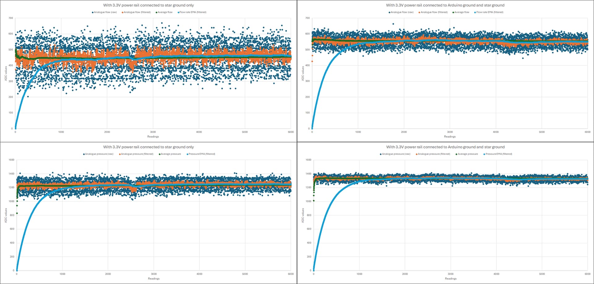
***ETA2: Connecting ground
I had the breadboards and Arduino connected using a star ground, but I decided to connect the 3.3V power rail ground (i.e., where the RC low-pass filter and voltage dividers connect), and connect it to the ground next to the AREF pin on the Arduino to see what would happen, and it significantly cleaned up the noise in the signal. I also connected the ground from the 5V power rail in my setup, and it cleaned the signal up even more (though this isn't shown in the graph below).