Hello from Italy.
I want to make a sliding door mechanism for the door in my lab.
The goal is to:
Press a button from one side of the door;
The door should close afte X time;
If pressed two time the door should stay open;
Press another button from the other side of the door.
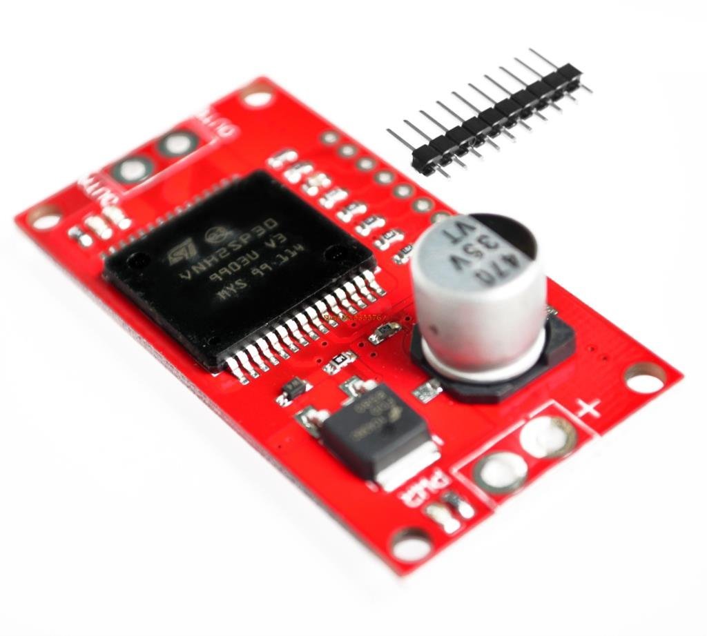
I already have in the house and Arduino UNO and a board with a single motor driver vnh2sp30 a wiper motor from BOSCH and of course wires and whatnot.
My experience wi A is very limited and the basics of electronic too..
If you want to help it's appreciated
Here's a video of the awesome animation (like it's very difficult to understand)
I was just whatching that! And referencing to his list of symbols i have some questions:
Are K1A and K2a Solenoids?
K1B,K2B and K2C switches?
S3 and S4 push buttons?
And i quite did'nt get Q1 and Q2
Also this scheme come with some code to look at? Thanks again
i think i'm at 50% of the understanding of the logic scheme.
i'm more familiar with the concept of a relay instead of transistor's. need more research!
i also couldnt find what TVS1 is. Transformer maybe?
Ok, so. I'm making progresses i think. I have some other questions:
1)relays are phisically separated from themself in the circuit drawing (solenoid and the switch) right? In reality they are a one component but i think it's the standard rappresentation for drawings.
2)Everytime S3 or S4 are pressed both D7 and D8 are outputting signal right? One that open the gate K1B and the other that switch polarity for the motor depending on the limit switch state?
3)at this point isn't arduino a bit useless for only outputting 2 signals that they even triggered by an external sourrce (buttons)? (poor guy!)
If that's the case i think i understood the diagram.. so the other questions is:
4)are there PCB already designed for this on sale? Or would be a better idea (or funnier) to make it myself?
5)Or else ditch "en masse" relays and use only inputs and outputs from arduino(less practical maybe?)
I almost forgot about the vnh2sp30 motor driver. Is it useless?
1)relays are phisically separated from themself in the circuit drawing (solenoid and the switch) right? In reality they are a one component but i think it's the standard rappresentation for drawings.
The relays in the schematic are drawn in a heterogeneous fashion as it makes the schematic easier to follow and read.
You can think of the relay coil as physically separate from the contacts giving galvanic isolation from input to output.
Relays are one component.
2)Everytime S3 or S4 are pressed both D7 and D8 are outputting signal right? One that open the gate K1B and the other that switch polarity for the motor depending on the limit switch state?
This depends entirely on what your control software does.
For example, you could write code to ‘pick’ K1 when K2 is ‘dropped’. picked=ON=energized dropped=OFF=de-energized.
This could happen at 3 in the afternoon or what ever.
You could write code to look at S3 to see if it was pressed ‘5 times in a row’, then if so, pick K2 then K1 to reverse the direction of the door motor.
3)at this point isn't arduino a bit useless for only outputting 2 signals that they even triggered by an external sourrce (buttons)? (poor guy!)
Software in the Arduino makes control of outputs and input sampling easy.
Software is easily changed and added to as needed.
An Arduino is not always needed, it’s all up to you and your requirements.
If that's the case i think i understood the diagram.. so the other questions is:
4)are there PCB already designed for this on sale? Or would be a better idea (or funnier) to make it myself?
If you have a few construction skills, it’s very simple to wire ccts. like this on breadboard material.
5)Or else ditch "en masse" relays and use only inputs and outputs from arduino(less practical maybe?)
To drive high current loads, you need drivers like transistors, relays, solid state drivers.
The Arduino itself is very limited in its drive capabilities.
I almost forgot about the vnh2sp30 motor driver. Is it useless?
You can use one of these, it’s all up to you and your abilities.
I suggest new people use a simple relay cct. for: low speed, not often operated, applications like this.
Often what happens with a motor driver and a noob is something gets miswired, shorted, or there is static discharge rendering the motor driver dead.
Thanks again Larry for taking your time to teach me (and i hope others too)!
In the end your drawing is all i need to complete the task?
I'm defentely buying all the parts this week and give it a try!
I also stumbled upon this video Creepy Creations - Wiper Motor Control - YouTube and i understood more the need to ditch a motor driver and use relays instead.
I'll let you know my progress!
I have one more question: i'll be able to program arduino to make the task where i want the door open forever instead of "X" seconds ? Like a double press button? I'm sure it's possible
larryd:
EDIT
Looks like your motor draws much more current than mine does, mine draws ~1 amp (with a stall current of 3 amps).
Just seen the current ratings in the data sheet for your motor, they seem high.
Please confirm your motors running current under load, and the motor’s resistance. (different relays and transistors may be necessary).
I tried measuring without load and it seems to draw .40 mA . Is that possible ? seems very low!
Sincerly i dont know how to measure it in high load because the reduction is very strong and even by hand i'm not able to restrain the chuck/spindle. Do you ideas how to do it ?
I tested with a simple 5A (directly) source and all seemed(!) fine .. nothing was hot but there was no load