Out of curiosity I ordered a PZEM-004T module from China.
This module can measure RMS voltage, RMS current, active power and total energy usage over time and has a opto-coupled TTL serial connection to get the values remotely. Great if you want to interface it with an Arduino or something like that.
For less then 10 euro it's a bargain ![]() and I have seen some projects that uses this module.
and I have seen some projects that uses this module.
Unfortunately the PCB design sucks ![]() In my opinion it is unsafe
In my opinion it is unsafe ![]()
The creepage distance between the opto-coupler and serial output pins and the mains is a miserable 0.25mm. As the module is rated for 260V this should be 2.2 mm minimum.
The resistor that is used as voltage divider for the chip is a 1 mega ohm MCR10 SMD resistor that is rated for 150V voltage drop maximum. As the peak voltage at 260V is ~370V this resistor should be replaced with preferable four 250 kilo ohm resistors in series.
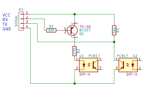
To make it at least a little bit safer I desoldered the serial connector and the opto-couplers and I made a second PCB and used the opto-couplers to connect the main PCB to the second PCB. Now there is plenty of space between the mains and the interface ![]()
I also added a transistor to drive the RX opto-coupler. It now works at 5V and 3.3V with a FTD1232 module and the maximum current during operation is 7 mA at 5V and 4 mA at 3.3V. The modification was made with components at hand so any advice to improve upon this solution is welcomed.
I also made a small PCB for the other end to use a normal resistor and a connector to expose the voltage input of the board. Now it should be possible to measure the current through and the voltage over a load that is controlled with a triac controller. At this moment this is untested.
I hope this is useful ![]()