I am using PZEM004T v3 100A since long time now. Both with esp32 and arduino.
I am facing issue with its 100ohm 1watt resistor buring up if i keep it up and running for few hours.
I fried 10+ modules so far just while testing, no short circuit nothing, just heating up and buring automatically.
Is it a global issue, or they are not just built to keep running for that long.
I tried replacing that resistor with other 100ohm 2watt and 5watt, but they are not ready to work again.
Looking for help with hardware here.
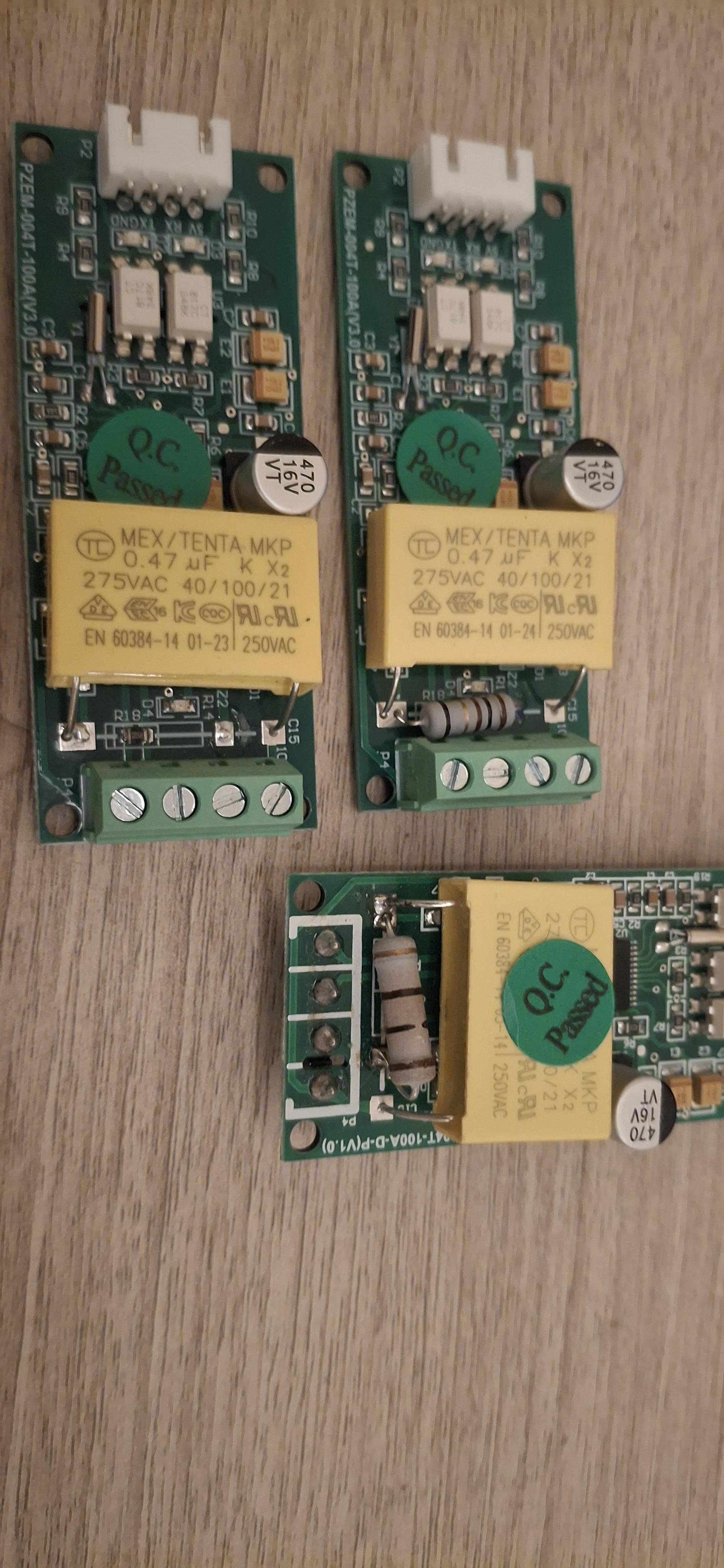
Attaching images of few modules.
The resistor seems to be the burden resistor for the connected current transformer, and must match the transformer used. The resistor heats up from the current through the ringcore, not from the PZE module itself.
What are the specs of the CT and what current are you sending through it.
Not sure why you mention 100 Ohm, the PZE datasheet states 0.05? for that resistor.
Leo..
The first thing is to validate you have the correct module. With that many failures something is not as stated. How much current are you passing through the CT?
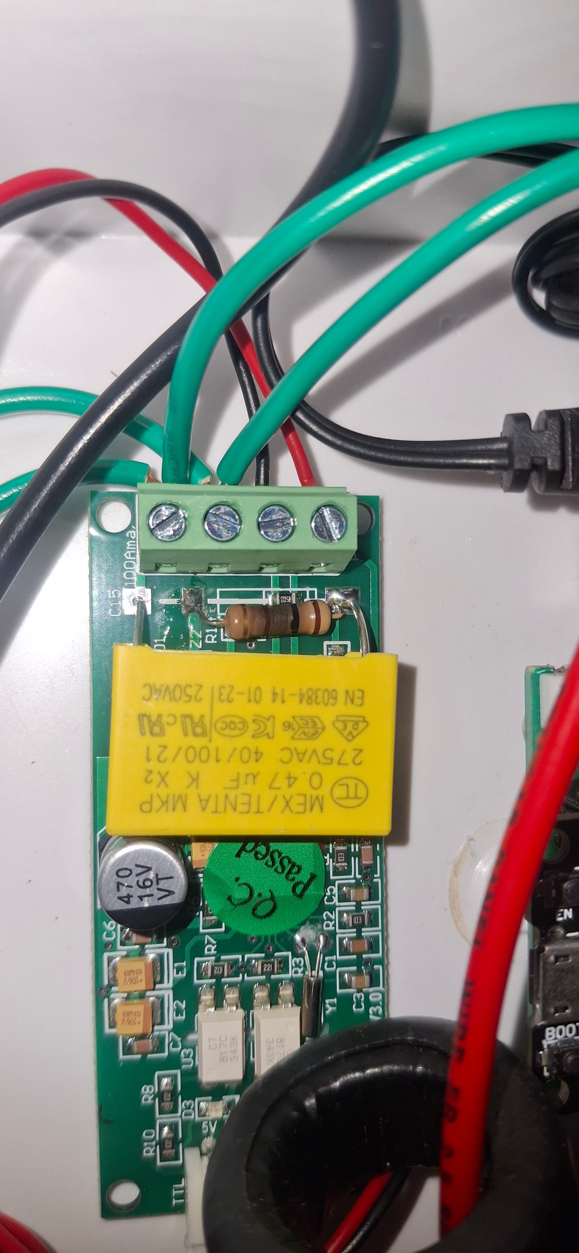
I clearly see a black ringcore current transformer in the image.
With a red wire passing through it.
Question is which one, and if 100 ohm matches this transformer and mains current.
Again, the 100 Ohm resistor has nothing to do with the module and everything with the CT.
Leo..
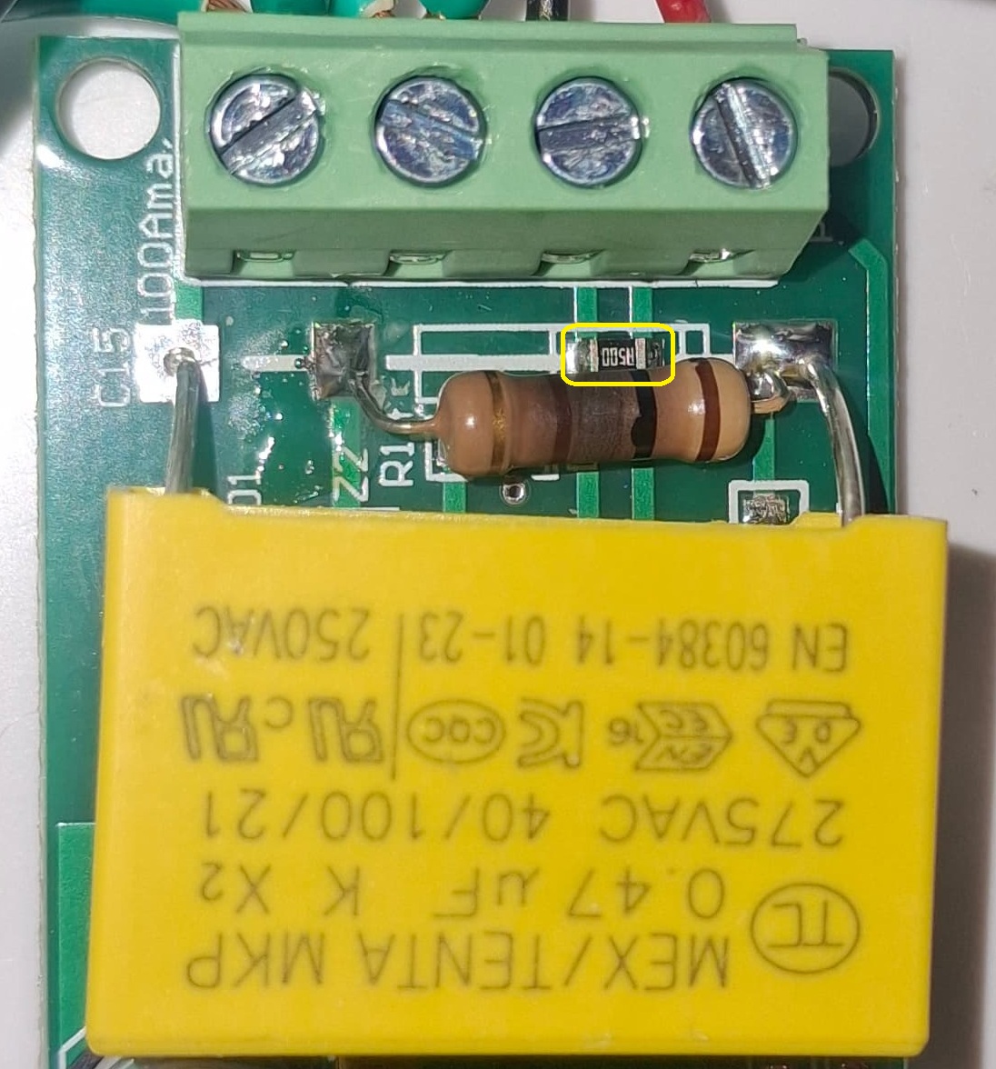
If you look at the last photo from post #1, you can see that the 100Ω resistor has been pushed over slightly, and the burden resistor (SMD) can be seen underneath it. The burden resistor fitted is 0.5Ω.
At 50Hz, the 470nF capacitor has a capacitive reactance (Xc = 1/2πfC) of 6773Ω.
From a 240V 50Hz supply input the current will be limited to 35mA, (or in practice less as there are other components in series with the capacitor).
With 35mA flowing through it the power dissipated in the 100Ω resistor should only be around 126mW.
My guess is that the 470nf capacitor or the 470kΩ bleed resistor in parallel with it are breaking down and allowing a higher current to flow causing the 100Ω to burn out.
So that's either a defective 100A batch, or a fake 100A made from a 10A model.
In both cases I'd ask for a replacement and/or and change supplier (China?) by choosing a more reliable one.
Ahh. I see now. It's part of the capacitive supply of the chip.
The 100 Ohm resistor shouldn't burn from the small current of the 470n cap.
Maybe OP connected the mains and CT to the wrong screw terminal.
We can't see where the wires are going on the images in post#1.
Leo..
PS; That yellow 0.47uF cap will likely fail after a year.
All those X-type caps gradually drop their value until almost no capacity is left.
Looking at the diagram again, R7 can only overheat through the big yellow 275volt cap. You're not doing something silly like powering the board from a higher (3-phase) mains voltage?
Leo..
I am using 220-260V AC.
And the module is definitely a V3 with 100A CT.
Further, I have getting current reading od volatage, current, pf, frequency, energy, power when i power up the module.
I have purchased modules from different suppliers as well.
Still the resistor (the metal oxide one 100ohm 5% tolerance) is burning up even at lower current loads.
But my main concern is when i replace the burnt resistor with other new one of 100ohm, it stops showing reading in my console.
is this a three phase system?
could you have connected the N and L lines between two of the phases (typically 415volts AC)
on my PZEM-004T 100amp capacitor C15 0.47uF is rated at 275VAC
applying 415volt across N and L would certainly cause problems damaging C7 and hence burn out R7 100ohm resistor
what readings do you get? how do they compare with multimeter/current clamp meter?