why not just monitor the input and capture the timestamps and state when the state changes.
it's still unclear to me what the encoding scheme it. you said macnchester.
but binary without a clock only works for a limited # of bits before the timing can drift too much. This is why UARTS only suppot 10bits (start, data, parity, stop)
Manchester coding should make it easy to recover the original clock. Important are only the transitions which occur on the falling edge of the original clock, so there are ample opportunities to re-sync with the clock.
My problem was only understanding the format of the payload which the OP was attempting to send over this "Manchester" encoded link and this is now clear from post #33
Yes i was trying to read out the pins first to get my timing from the pins themselves, but i cant get it to work. Witch the designated times i got from my millis, it read out just fine, but if for example the wave isnt perfect it will fail very quick, so thats why i wanted to know if anyone had reliable code useing the updatein() command.
I apologize if this has already been addressed. In the code in post #1, there's only one place where the signalIn pin is read, and that's after waiting a period of time. But I don't see anything that determines when to start counting? At the beginning, maybe in setup(), there should be something that waits for a change on D2 to indicate that transmission has started. I don't see that. Well, maybe I'm just missing it.
A two channel scope could be used to see if you are actually reading D2 when you think you are. Add code at the beginning of readHalfBitStable() to output high on D4, and then bring it back low just before the return. With one scope probe on D2 and the other on D4, you can see when you are reading D2, which is when D4 goes back low.
Timer1 is set to capture the current timer count on each transition on D8, which is where the incoming signal is fed in. The edge that triggers the capture can be toggled in a register. Each capture event also triggers an interrupt.
There are two circular buffers. One contains the actual elapsed times between transitions.
The second buffer contains the incoming half-bit readings - either a one or a zero for each buffer entry. The buffer is filled by the timer1 capture ISR. Starting with an assumed initial half-bit data time, the ISR calculates the elapsed time since the previous interrupt. If it is about equal to a half-bit time, a single byte is added to the circular buffer equal to the state of D8 before the transition occurred - either a one or a zero. If it's about twice that time, two bytes of that value are added to the buffer.
So the ISR reads the captured timer1 count, subtracts the previous count, saves the elapsed time value to the first buffer. Then puts either one or two bytes into the second buffer depending on how long the elapsed time was, toggles the interrupt edge, and then returns.
Meanwhile back at the ranch, loop() in a leisurely manner reads in the stream from the second buffer two at a time, and Manchester decodes the pair to a one, a zero, or illegal, and then does whatever it needs to do with that information.
Loop() also does some kind of running average on the data from the first buffer, and uses that to adjust the assumed half-bit time to reflect what is actually happening if it diverges too much from what's currently being assumed.
I haven't thought through what happens if polarity is unknown or if the first bit is a zero. But that presumably wouldn't matter in this case.
The transmission wave is sent over to the code in manchester encoding, it has 2 headers that stay the same. These are followed by the data, the first data that gets through are how many coordinates will be sent out, followed by the coordinate pairs. The second data is the frequency. All the data needs to be translated, first from the manchester encoding, and then to a few decimal values. The frequency of the transmitter is 100hz, or 10ms. Encoded this will be 5ms for a low and 1ms for a high, in the manchester encoded scheme. Here we use the standard 10 and 01 to represent a 1 or 0. This is because the transmitter can vary from time to time, so with manchester encoding we can sync up the wave more easily.
But my code runs perfectly for the test transmitter ive made. But if i plugged it in into my real transmitter. And i think its because a high and a low dont have the same lenght. The lows are a bit shorter. So i thought to try and fix this by using the updatein() function, but it wont work for me. So if anyone has any solutions for this, that would be tremendous for me.
i don't beleive this is the appropriate method for decoding Manchester bits.
it's fair enough to start with a nominal pulse period and use a threshold of ~1.5 that nominal period to recognize one of two possible width indicating either a repeat or change in the bit state.
it's fair enough to start with a nominal bit timing, over sampling by 2 (i.e. sample 2x per bit period) but sampling at the 1/4 and 3/4 points within the it period and constantly resynchronizing based on that rising edge of a 1 bit. This implies recognizing the rising edge as well (kinda like a UART waiting for a Start bit)
a 1 bit is HIGH at the 1/4 point and LOW at the 3/4 point. visa versa for the 0 bit
the code should constantly update its pulse period estimate.
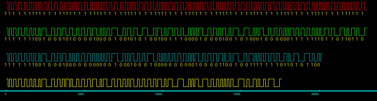
here's a zoom in of the middle section showing 1/0 transitions. the bit value marks the middle of the bit period which starts with the bit value but inverts halfway thru the bit period. (a bit period is 2 units)
here's an exagerated example of how the timing can vary, yet the data can still be decoded by constantly updating the bit timing based on the timing of the data as it is received
Is the current situation that your code from post #39 works against your test transmitter code which appears in post #35, however, it does not work against the transmitter which your professor has provided for this exercise ?
If that is the case, it is very possible that your professor has done a few tricks, within the limits of Manchester encoding, to make this exercise more challenging, such as varying the timings within a certain tolerance etc. which would require some better attempt at clock recovery/re-syncing in your code.
Anyway, can you somehow get an oscilloscope picture of the output of this "difficult" transmitter?
thinking about this further, i think it becomes simpler to time the period between edges. edges, both rising and falling are either 1 or 2 half periods apart. the encoded data is either HIGH or LOW for either 1 or 2 half periods. the bit state changes when that period is 2 half periods
recognizing edges and the periods between edges avoid sampling the actuale signal state, HIGH/LOW at specific points
Yeaa, i dont have access to an oscilloscope right now, but from what i could see was that the low pulses were shorter than the high pulses. The professor said that the code they made could have some timing issues, but he also said that if i were to work with Pulsein() for example, that that would work more often, because then youre relying less on very tight timing, and more on the pulses themselves. Im stuck there because everything ive tried so far isnt working.
I am beginning to not like this professor person. I've had some better than others, but nary a sadist in the bunch.
The OP seems ill-equipped to handle this approach. As evidence I point to this thread… I don't know how we did things like this just sitting in the lab, no AI, no crew of selfless experts, enthusiasts and talented amateurs spending what little time they may have left on something like this.
It's fun to struggle with a puzzle, I do them for fun. As a practical matter, puzzles encountered during development are opportunities for changing direction.
Is use of Manchester encoding mandatory? Could this professor person's game have been to suggest something that is not appropriate, and the lesson be that one should do some research before locking into a distraction?
FWIW there is mention on this thread of a serial comms library based I think on SoftwareSerial that implements Manchester encoding at a low level. Perhaps it could be used, or used as a source of a somewhat different way to do the thing, if Manchester must be something you have to say you did in order to get a passing mark.