It might be pretty clear what you think you're doing, and if so, the following comments are appropriate, but we'll never know because there's too much ambiguity. So, chew on the following.
your 5-way switch defines one common pin(row), and 5 'columns'. Fine. Now, you have five other contacts (three buttons, two sides of an SPDT). Fine, wire one side of each button, and the common of the SPDT, together. That's a second 'row'.
That pot/pot/button needs separate wiring.
where's the second side of the switch, for wiring to your 'matrix'? It's either 5V or gnd, so it can't be wired to a matrix.
the two pot signals need to go to individual analog inputs (A0, A1?), so they can be read unambiguously. So do it that way.
Total I/O - 5x2 for matrix, one DI for the button on the joy, and two AI for the joystick values.
There may be ways to merge some of this mess, but I'd go for simple and wire it like that.
In future, please do as others are suggesting, and provide a better schematic, as well as better information about the devices.
Caveat - my crystal ball is old, cracked, dusty, and the magic has leaked out, so if I've misinterpreted some of your info, attribute it to that; I did the best with what you provided.
C
no code yet, I wanted to make sure the wiring was correct first. I never mentioned I was looking for code help at the moment. Just where you recommend getting beginner help. You mentioned tutorials, guides, and reference documents.
your 5-way switch has 5 contact outputs and one common pin.
your joystick has 5V, ground, pot output x2, and button x 1 - where's the second connection for the switch, which is needed if the switch is to be incorporated in a matrix?
You gave a link for your five-way, but clearly the joystick isn't fully understood. if you think you can include it in a matrix.
You may need to research matrix scanning a bit more, so you understand my comment. That joystick button must have, as it's second pin, an internal connection to 5V or GND, or possibly to one, the other, or both pot signals, though I've never seen that done, nor can I imagine why it would be done. But a spec sheet would illuminate..
C
How many pins are available, after you assign non-button related hardware? It would be easier to interface most or all of the switches with individual I/O pins.
If you know next to nothing about software, a matrix is going to drive you crazy.
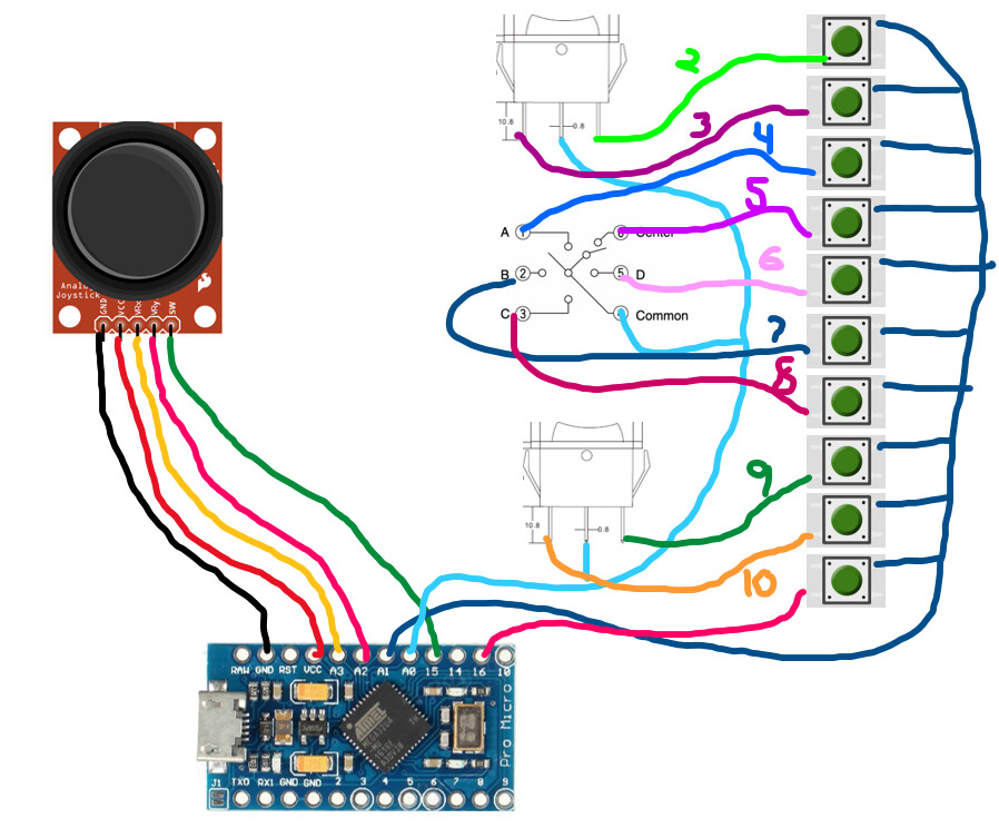
I do not know what I was thinking... the joystick does not act like the other components. Like I said I tried to figure out the joystick and 5way on my own. I was not able to find examples.
There are many version of hardware being used on this. Some iterations use 20 buttons, some joystick/5way/4 buttons/1 rocker. It varies. I do not think all combinations will work without a matrix. Some will yes, but I fear not many will.
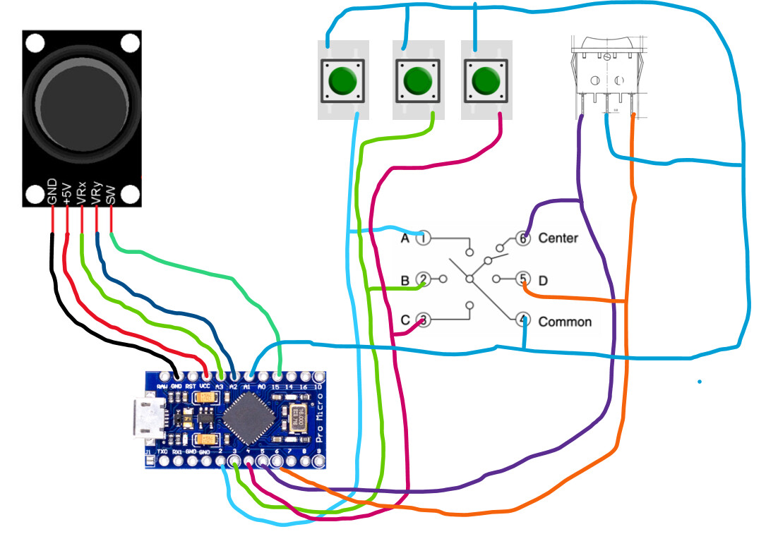
Here is an updated picture. I am a little confused on this...
Why would each of the buttons and SPDT need their own common? I believe the picture is shown as a 1x5 matrix now.
If you have a 1x5 or a 1x(anything) matrix, it's not a matrix. You might as well ground the "1x" and just read the 5.
I think I see the error Camsysca mentioned. Your wiring shows no difference between a green button press and a rotary switch selection. Also if you have any constantly on contacts in a matrix, it will interfere with other switches in the matrix, unless diodes are used.
Supposing the rotary switch is set to "A". That connects "Common" with "1", which is a direct short across the first green button.
A 1x5 matrix has a common pin for 5 of the buttons; a 2x 5 matrix has two such arrangements, where the second 5 connections are the same as the first 5, but a second common links that 5 switches.
this is for a friend, I have the 3D printer and the modeling program. That part is done I am just waiting on his final hardware selection. I am using this diagram as an example of a possibility. I will mock up hardware I would choose if this was for me.
I do understand that a 1x5 matrix... and I thought I needed a 2x5 because of the joystick. But now that I understand the joystick better, I understand a 2x is not needed.
This is also something I read about. But I am only concerned about the 5way being an issue with this. This is primarily a thumb button box, so unless you have 2 thumbs on one hand you would only be pressing one button at a time. The 5 way is a little different because you could want to press left, but you could also bump into the down and pressing down. (3 selections when only 1 was desired)