Hello Msquare, TomGeorge, Paul_B and the arduino forum,
The code which came from
http://playground.arduino.cc/Main/LedControlDemos#LedMatrixDemo
is copied herewith below.
is called LCDemoMatrix.ino
I do have a DMM and can check voltage but am not sure what to look for.
The polarity of the LEDs were checked as they were put on the
breadboard using a resistor and battery.
The chip is Maxim7219.
What I did was
- Load the sketch onto the Arduino
- Build the bread board exactly (checked it four times)
as shown in the pictoral titled "Max7219 to Arduino for Linear Display" above.
- Plugged into the Arduino Uno wall wart.
- Result: two LEDS on the Arduino Uno came on but none of the LEDs on the bread board
do anything after observing for a couple of minutes.
I realize that the sketch is for a matrix display. I am hoping to observe
what the sketch did to the setup and see what it did to my setup and
use observation to light up the first, then the second, then the third
LED. The display that will be built eventually will have 320 LEDs and
daisy chain five 7219s.
But right now I just trying to get one LED to come on.
For instance, if I could just light up the LED marked "DP"
that is closest to the 7219 chip in the pictoral
titled "Max7219 to Arduino for Linear Display" above.
For, instance lines 44, 45, and 46 from LCDemoMatrix.ino
/* now display them one by one with a small delay */
lc.setRow(0,0,a[0]);
lc.setRow(0,1,a[1]);
I think the first zero after the open parenthesis is the
row, the second zero is the column and the 'a[0]'
is the boolean. But if that is correct and the
boolean equates to true, then that should light the
LED marked "DP" that is closest to the 7219 chip in the pictoral
titled "Max7219 to Arduino for Linear Display" above
but it does not.
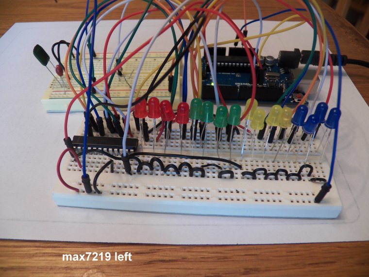
The pictures requested of the breadboard are here.
But I don't think they convey as much info as the
pictoral.
One thing that pictures do show is the reason
why two breadboards are used is because there is
not room on the largest board in my stash for
all the components. I will get a bigger board
and try Paul_B's suggestion. Or I could take a few
of the LEDS off to make room since all I am shooting
for is a 'Hello World' so I could use twelve instead 16 lights.
The capacitors are, at least electrically, as deployed
in the schematic shown at the top of

I guess proximity could make a difference but
it doesn't seem like it would make enough difference
to totally negate all result.
Thanks for your help. I believe the display will
be beautiful when complete and promise to publish a video of the
result.
Allen Pitts, Dallas Texas
//We always have to include the library
#include "LedControl.h"

/*
 Now we need a LedControl to work with.
 ***** These pin numbers will probably not work with your hardware *****
 pin 12 is connected to the DataIn
 pin 11 is connected to the CLK
 pin 10 is connected to LOAD
 We have only a single MAX72XX.
 */
LedControl lc=LedControl(12,11,10,1);

/* we always wait a bit between updates of the display */
unsigned long delaytime=100;

void setup() {
  /*
   The MAX72XX is in power-saving mode on startup,
   we have to do a wakeup call
   */
  lc.shutdown(0,false);
  /* Set the brightness to a medium values */
  lc.setIntensity(0,8);
  /* and clear the display */
  lc.clearDisplay(0);
}

/*
 This method will display the characters for the
 word "Arduino" one after the other on the matrix.
 (you need at least 5x7 leds to see the whole chars)
 */
void writeArduinoOnMatrix() {
  /* here is the data for the characters */
  byte a[5]={B01111110,B10001000,B10001000,B10001000,B01111110};
  byte r[5]={B00111110,B00010000,B00100000,B00100000,B00010000};
  byte d[5]={B00011100,B00100010,B00100010,B00010010,B11111110};
  byte u[5]={B00111100,B00000010,B00000010,B00000100,B00111110};
  byte i[5]={B00000000,B00100010,B10111110,B00000010,B00000000};
  byte n[5]={B00111110,B00010000,B00100000,B00100000,B00011110};
  byte o[5]={B00011100,B00100010,B00100010,B00100010,B00011100};

  /* now display them one by one with a small delay */
  lc.setRow(0,0,a[0]);
  lc.setRow(0,1,a[1]);
  lc.setRow(0,2,a[2]);
  lc.setRow(0,3,a[3]);
  lc.setRow(0,4,a[4]);
  delay(delaytime);
  lc.setRow(0,0,r[0]);
  lc.setRow(0,1,r[1]);
  lc.setRow(0,2,r[2]);
  lc.setRow(0,3,r[3]);
  lc.setRow(0,4,r[4]);
  delay(delaytime);
  lc.setRow(0,0,d[0]);
  lc.setRow(0,1,d[1]);
  lc.setRow(0,2,d[2]);
  lc.setRow(0,3,d[3]);
  lc.setRow(0,4,d[4]);
  delay(delaytime);
  lc.setRow(0,0,u[0]);
  lc.setRow(0,1,u[1]);
  lc.setRow(0,2,u[2]);
  lc.setRow(0,3,u[3]);
  lc.setRow(0,4,u[4]);
  delay(delaytime);
  lc.setRow(0,0,i[0]);
  lc.setRow(0,1,i[1]);
  lc.setRow(0,2,i[2]);
  lc.setRow(0,3,i[3]);
  lc.setRow(0,4,i[4]);
  delay(delaytime);
  lc.setRow(0,0,n[0]);
  lc.setRow(0,1,n[1]);
  lc.setRow(0,2,n[2]);
  lc.setRow(0,3,n[3]);
  lc.setRow(0,4,n[4]);
  delay(delaytime);
  lc.setRow(0,0,o[0]);
  lc.setRow(0,1,o[1]);
  lc.setRow(0,2,o[2]);
  lc.setRow(0,3,o[3]);
  lc.setRow(0,4,o[4]);
  delay(delaytime);
  lc.setRow(0,0,0);
  lc.setRow(0,1,0);
  lc.setRow(0,2,0);
  lc.setRow(0,3,0);
  lc.setRow(0,4,0);
  delay(delaytime);
}

/*
  This function lights up a some Leds in a row.
 The pattern will be repeated on every row.
 The pattern will blink along with the row-number.
 row number 4 (index==3) will blink 4 times etc.
 */
void rows() {
  for(int row=0;row<8;row++) {
    delay(delaytime);
    lc.setRow(0,row,B10100000);
    delay(delaytime);
    lc.setRow(0,row,(byte)0);
    for(int i=0;i<row;i++) {
      delay(delaytime);
      lc.setRow(0,row,B10100000);
      delay(delaytime);
      lc.setRow(0,row,(byte)0);
    }
  }
}

/*
  This function lights up a some Leds in a column.
 The pattern will be repeated on every column.
 The pattern will blink along with the column-number.
 column number 4 (index==3) will blink 4 times etc.
 */
void columns() {
  for(int col=0;col<8;col++) {
    delay(delaytime);
    lc.setColumn(0,col,B10100000);
    delay(delaytime);
    lc.setColumn(0,col,(byte)0);
    for(int i=0;i<col;i++) {
      delay(delaytime);
      lc.setColumn(0,col,B10100000);
      delay(delaytime);
      lc.setColumn(0,col,(byte)0);
    }
  }
}

/*
 This function will light up every Led on the matrix.
 The led will blink along with the row-number.
 row number 4 (index==3) will blink 4 times etc.
 */
void single() {
  for(int row=0;row<8;row++) {
    for(int col=0;col<8;col++) {
      delay(delaytime);
      lc.setLed(0,row,col,true);
      delay(delaytime);
      for(int i=0;i<col;i++) {
        lc.setLed(0,row,col,false);
        delay(delaytime);
        lc.setLed(0,row,col,true);
        delay(delaytime);
      }
    }
  }
}

void loop() {
  writeArduinoOnMatrix();
  rows();
  columns();
  single();
}