I found out in a hurry that the matrix does not fit in a breadboard. I'm not sure how to get around that at the moment.as i don't have any wire, just jumpers and I only have one half breadboard.
Also the wiring diagram is a little confusing I know you need 1 resistor and a cap, but not sure how to wire them all the diagrams i have seen are pretty confusing. was wondering if anyone had a fritzing diagram of the set up with an Arduino that they could possibly share?
use the datasheet of your display and connect each column cathod pin to each "dig" pin of the MAX7219. (row 1 -> "dig 0", row 2 -> "dig 1"etc)
after that connect each row anode pin to each segment pin of the max7219 (row 1 -> seg a, row 2 -> seg 2" etc.
find the right current set resistor, connect the IC to your platform and it's done
pixel forward current is 20mA but you must think of the total power dissipation and a protective value if the scan duty cycle is too slow during programming tests. A 10mA is more conservative value for test. so Rset must be a 62K resistor. (after if all works fine and the duty cycle is set you can decrease the Rset value to increase the led current. the maximum allowed current is 500ma divided by number of pixels (8 units) and duty cycle. You can decrease the value to 15K I think).
Don't forgot to use a 100nF and at least 10uF caps near the power supply pins (19 and 9) of the maxim IC as a local current tank.
connect the CLOCK, DIN and LOAD pins to your arduino platform. best if connected to the SPI bus (SPI UART is faster than bit twidling)
DOUT can be left unconnected if no daisy chain is used.
I've done a google search after that and i've foiund this:
but be careful if you want to use an allready made library you must be sure of the right wiring order.
Pedro147 are you sure about the 1K resistor value? seems very low compared to the mine and defined with the datasheet. (page 11 where 9.69K is the lowest value defined for 3.5 Vf voltage and 40mA If current ) -> 1K is very low! and give very high current (can destroy the led and/or the chip)
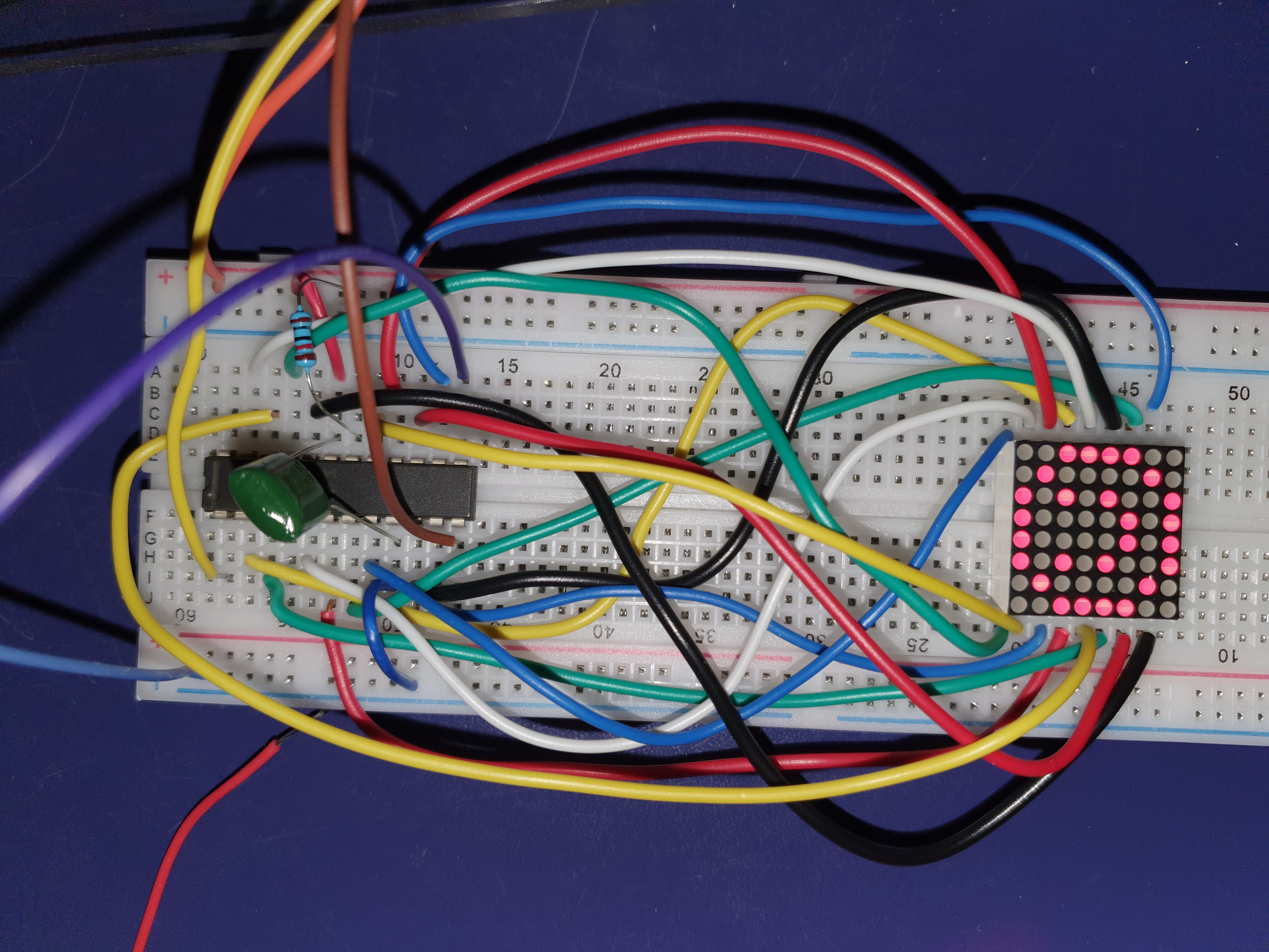
Well, if you can fix it that easily in the code, it should take seconds to fix the wiring by making the equivalent changes. Maybe post a picture of your wiring. One where we can trace exactly where every wire starts and ends. If you find you can't take a clear picture showing where each wire goes, then I think we may have located the problem.
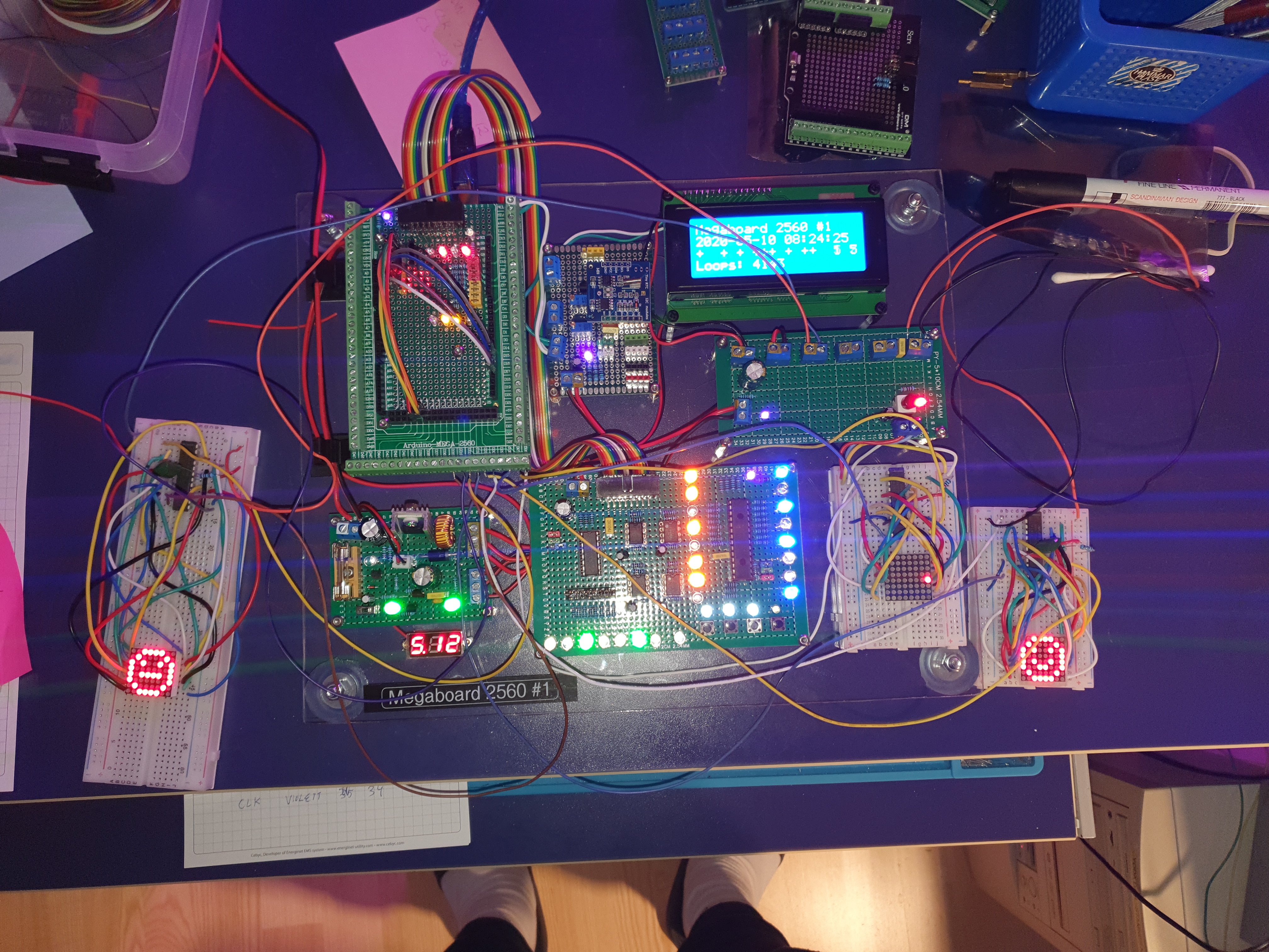
I have made three different boards using a matrix and a max7219 (starting from scratch each time). Carefully checking the wires. And a friend of my also checked it. We could not find any errors.
I'll see if I can make a picture of a cleaner version (the current one wires are overlaying each other so a picture will not show anything usefull right now).
But if the wiring was incorrect and shifted the rows, I must have misplaced 50% of the connections, which should be rather easy to spot.
This code fix it:
MyLedControl::MyLedControl(int dataPin, int clkPin, int csPin, int numDevices) : LedControl(dataPin, clkPin, csPin, numDevices)
{
}

void MyLedControl::setLed(int addr, int row, int column, boolean state)
{
  LedControl::setLed(addr, row, (7 == column) ? 0 : column + 1, state);
}

void MyLedControl::setRow(int addr, int row, byte value)
{
  byte b = (value & 0x01) << 7;
  b |= value >> 1;
  LedControl::setRow(addr, row, b);
}
Why do five different attempts give the same result? And why do the minor modification in SW (done by the derived class MyLedControl) fix this? The wiring cannot be completely wrong, can it?


