Hello, Im new to arduino and new member on this forum.
In my latest program that I made, I can obtain a diagonal line on a Led Dot Matrix as a test program, but its refresh rate can not be lower than 1ms as arduino is restricting. My MCP chip is minimum 100kHz (actually has higher values specified) which means 10μs per cycle. - Do anyone know how to lower arduino fv to μs instead of ms ?
In the movie here I present using it's internal fuction
delay(dly);
which is a ms function, I read about it and I get that. I tried also its other function as well, named
delayMicroseconds(dly);
and the result is exactly as the delay(dly); in ms and not under 1ms, to it's promoted μs.
This is a 2min video where I explain the entire problem, please watch it.
Thank you.
The MCP23017 can run at 400kHz. Standard I2C is 100kHz
If you choose the correct mode it can write 16-bits continuously in 2 I2C bytes. i.e. 2 * 90us = 180us. (45us @ 400kHz)
Of course the Arduino Wire library is not able to write continuously.
And I have not studied how your particular MCP23017 library works.
I have never used 8x8 Matrix displays. I guess that you can just write 16-bits to light a particular column. i.e. 8 x 2-bytes to write a complete frame. i.e. 1.440ms @ 100kHz.
Which means you can easily create a flicker-free display.
I have no intention of trying to read code from a video.
Please post your sketch properly. i.e. paste it to a "Code Window" in your message.
Hi, can you post the code? looking at the video gives me a bit of headache, just reply and use the 6th button in the upper "tool" line called "preformatted text". You just need to copy it. You will obtain something like this:
Thanks for the fast comments.
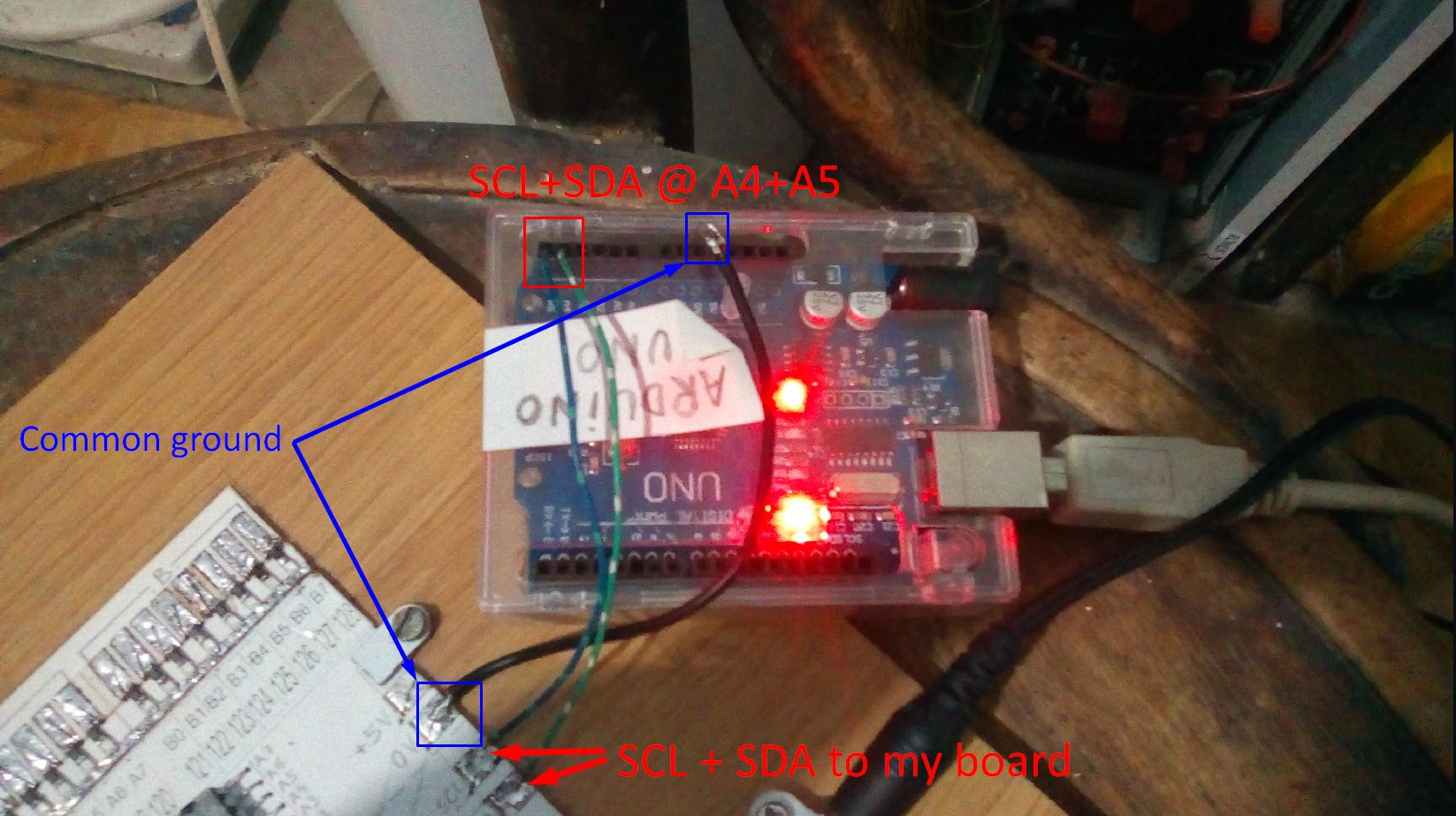
I failed to mention that I am using Arduino I2C from pinA4&A5 and a common ground. All these connected to a board of MCP23017s that I made, 8 of them.
MCP23017 datasheet mentions that it's I2C speed is at 100KHz minimum, which means 10us per cycle, but it has other higher speeds that I don't know for sure if they are applicable for it's I2C.
To follow the code itself and understand the pin decryption, please use this image I made about it and all will be clear. DOT-LED-MATRIX-DISPLAY-internal-matrix .jpg
Just to be clear! The code works fine. But it is slow because arduino is limiting everything to 1ms. Its my guess and my observation. - The problem is to bring down the flickering of the LEDs to appear as a single stright line, with no flickering whatsoever.
Thank you.
Im sorry for the multiple replies but it appears that new users are not permited to post multiple pictures and too much code in 1 single reply. Really? So I had to split everything in multiple replies.
I just google a bit and I find that "most humans can't easily distinguish individual frames at 30 hz."
So the visible fast flickering is really under 30Hz !
So the SCL pin from arduino is simply under 30Hz and not even close to 1ms which is 1000Hz. Hmmm, very strange.
Tell me what you see different, and I will clarify it.
Again, the code itself is working fine. The speed is too low, now that I am thinking of it a bit, it is visible flickering because the fv of the I2C pins are lower than 30Hz (as I already mentioned in the message before). I am not getting even close to 1ms. I believe that flickering is around 10 to 20Hz ! How to speed up this I2C port?
Thank you.
The simple answer is to put your once-off setup code into setup() and put your repeated code in loop()
You could use mcp1.writeGPIO() to write the whole 8-bits in one go.
The MCP23017 library is pretty stupid. It will create a fresh transaction for every call. Each transaction is multiple I2C bytes.
I guess that your display has 8 row-pins and 8-column pins.
And you write the "rows" of one vertical column at a time. Enable the appropriate column.
This is known as multiplexing. If you write fast enough you have lit the relevant pixels for your persistence of vision.
Of course a MAX7219 would look after the multiplexing in hardware.
You need to keep writing to each column continuously. e.g. every 4ms would mean 32ms for the complete frame or 31.25 FPS.
test it in your setup instead of one for loop (will give you 2 I2C writes instead of 16)
step 4:
see the datasheet of the MCP and find a better suiting mode for your application. For example, write both ports with two bytes
step 5:
if you want to multiplex a matrix, consider to use another chip, like an MAX7219 or HT16K33 which will do that multiplexing instead of your Arduino.
I folowed your advice and installed this 'blemasle MCP23017 Library' (exactly the one in your link) I find it in the Library Manager.
I also got a foot in the face as a beginner here in these forums and is not right and not pretty:
Really?
Is this absolutely necessary ?
Not cool !
Anyway... I hammered both my libraries for the MCP23017 last night and tried hundreds of permutations.
I actually listen to mister @david_prentice code advice and in my original code that I came here with, I optimize it as much as I could think of. And guess what? Now is running --a bit-- faster, faster enough to not flicker visible. But a tiny amount of flicker still exist, like a tiny vibration, but is not that evident as before. I switched to delaymiliseconds function and is kind of following the same level as the simple 'delay()' does. I concluded that the lines that are running in my code are eating a lot of time, from a couple of ms to tens or even houndreds of ms. Thats why the delaymilisecond() function has no effect. Your code markings helped me in this direction, to understand a part of this problem. So thank you (all).
I see another good suggestion from yesterday 'foot in the face', the use of
that @noiasca was very kind to put it in. Also good explanations. I will have to get into them as well.
Momentarily, I am beat up by staying all night and the rest of today until now on those libraries and literally discover what each fucntion does and tried hundred of permutations. I still did not find a complete solution using the blemasle library, only partial solutions for certain lines,rows and individual pins/Leds.
Using the library that I linked (which I never used), your Reset function should look like this
void Reset()
{
  mcp.portMode( MCP23017Port::A, 0b11111111 ); // set port A pins to inputs
  mcp.portMode( MCP23017Port::B, 0b11111111 ); // set port B pins to inputs
  //mcp.writePort( MCP23017Port::A, 0b00000000 ); // set port A pins to LOW
  //mcp.writePort( MCP23017Port::B, 0b00000000 ); // set port B pins to LOW
  mcp.write( 0b0000000000000000 ); // set all pins to LOW
}