MCUFRIEND_KBV library is working when using Arduino nano dev board but not working when using new esp32_nano development board. Please let me know what to do. thanks
1 Like
I'm told that the author of that library died awhile back, before the Nano ESP32 came on the scene. You'll either have to check through the existing forks of the library to see if someone else has added that board, do it yourself, or find another library.
I've moved your topic to the Display section of the forum as I think that it might get the attention of those that might know.
1 Like
Everybody seems to know what this boards is, but not me. And I am too lazy to search...
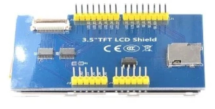
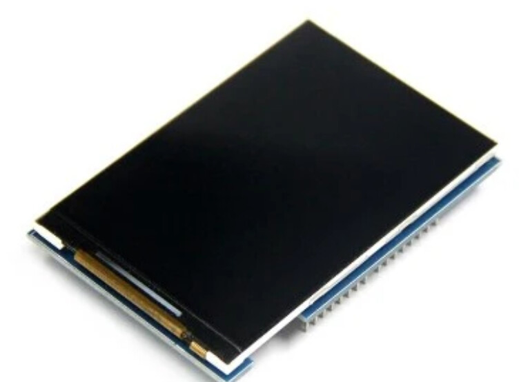
Nobody knows which display you try to use. Please post a link, ot a picture of the backside.
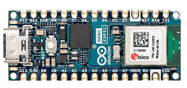
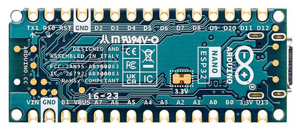
This is the new esp32 nano board.
ABX00092 Arduino | Development Boards, Kits, Programmers | DigiKey
I think that MCUFRIEND_kbv supports your display with ESP32 boards that have the Arduino UNO form factor and pinout.
You could try to use the same pins. But you need to configure the library. See
HOW TO INSTALL AND USE: is now in "mcufriend_how_to.txt"
You could also try with TFT_eSPI or Arduino_GFX.
I thought i can just replace my old arduino nano with esp32_nano to have an upgrade. The mcufriend_kvb library was working with the tft lcd display and the old arduino nano. I do not know what to edit in the library. I need some help please..
I think there should be an update on the esp_32 packages but i do not know where to start... please help..

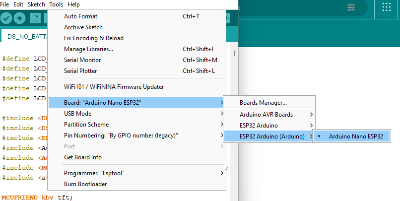
I would need to know which board you select to compile for.
Start here: https://github.com/espressif/arduino-esp32/blob/master/boards.txt
then search for the board you select.
In there you then find the variant used, e.g.
I am lost here, because this file is so long, and I didn't update, so the github version is different than the local version.
but in the pins_arduino.h you should see the mapping from pin names to GPIO numbers.
Ok. Maybe this entry: at line 38672
##############################################################
nano_nora.name=Arduino Nano ESP32
nano_nora.vid.0=0x2341
nano_nora.pid.0=0x0070
nano_nora.upload_port.0.vid=0x2341
nano_nora.upload_port.0.pid=0x0070
it has:
nano_nora.build.variant=arduino_nano_nora
nano_nora.build.board=NANO_ESP32
nano_nora.build.code_debug=0
See https://github.com/espressif/arduino-esp32/blob/master/variants/arduino_nano_nora/pins_arduino.h
// primary pin names

#if defined(BOARD_HAS_PIN_REMAP) && !defined(BOARD_USES_HW_GPIO_NUMBERS)

// Arduino style definitions (API uses Dx)

static constexpr uint8_t D0 = 0;  // also RX
static constexpr uint8_t D1 = 1;  // also TX
static constexpr uint8_t D2 = 2;
static constexpr uint8_t D3 = 3;  // also CTS
static constexpr uint8_t D4 = 4;  // also DSR
static constexpr uint8_t D5 = 5;
static constexpr uint8_t D6 = 6;
static constexpr uint8_t D7 = 7;
static constexpr uint8_t D8 = 8;
static constexpr uint8_t D9 = 9;
static constexpr uint8_t D10 = 10;  // also SS
static constexpr uint8_t D11 = 11;  // also MOSI
static constexpr uint8_t D12 = 12;  // also MISO
static constexpr uint8_t D13 = 13;  // also SCK, LED_BUILTIN
static constexpr uint8_t LED_RED = 14;
static constexpr uint8_t LED_GREEN = 15;
static constexpr uint8_t LED_BLUE = 16;  // also RTS

static constexpr uint8_t A0 = 17;  // also DTR
static constexpr uint8_t A1 = 18;
static constexpr uint8_t A2 = 19;
static constexpr uint8_t A3 = 20;
static constexpr uint8_t A4 = 21;  // also SDA
static constexpr uint8_t A5 = 22;  // also SCL
static constexpr uint8_t A6 = 23;
static constexpr uint8_t A7 = 24;

#else

// ESP32-style definitions (API uses GPIOx)

static constexpr uint8_t D0 = 44;  // also RX
static constexpr uint8_t D1 = 43;  // also TX
static constexpr uint8_t D2 = 5;
static constexpr uint8_t D3 = 6;  // also CTS
static constexpr uint8_t D4 = 7;  // also DSR
static constexpr uint8_t D5 = 8;
static constexpr uint8_t D6 = 9;
static constexpr uint8_t D7 = 10;
static constexpr uint8_t D8 = 17;
static constexpr uint8_t D9 = 18;
static constexpr uint8_t D10 = 21;  // also SS
static constexpr uint8_t D11 = 38;  // also MOSI
static constexpr uint8_t D12 = 47;  // also MISO
static constexpr uint8_t D13 = 48;  // also SCK, LED_BUILTIN
static constexpr uint8_t LED_RED = 46;
static constexpr uint8_t LED_GREEN = 0;
static constexpr uint8_t LED_BLUE = 45;  // also RTS

static constexpr uint8_t A0 = 1;  // also DTR
static constexpr uint8_t A1 = 2;
static constexpr uint8_t A2 = 3;
static constexpr uint8_t A3 = 4;
static constexpr uint8_t A4 = 11;  // also SDA
static constexpr uint8_t A5 = 12;  // also SCL
static constexpr uint8_t A6 = 13;
static constexpr uint8_t A7 = 14;

#endif

// Aliases

static constexpr uint8_t LEDR = LED_RED;
static constexpr uint8_t LEDG = LED_GREEN;
static constexpr uint8_t LEDB = LED_BLUE;

// alternate pin functions

static constexpr uint8_t LED_BUILTIN = D13;

static constexpr uint8_t TX = D1;
static constexpr uint8_t RX = D0;
static constexpr uint8_t RTS = LED_BLUE;
static constexpr uint8_t CTS = D3;
static constexpr uint8_t DTR = A0;
static constexpr uint8_t DSR = D4;

static constexpr uint8_t SS = D10;
static constexpr uint8_t MOSI = D11;
static constexpr uint8_t MISO = D12;
static constexpr uint8_t SCK = D13;

static constexpr uint8_t SDA = A4;
static constexpr uint8_t SCL = A5;

#define PIN_I2S_SCK    D7
#define PIN_I2S_FS     D8
#define PIN_I2S_SD     D9
#define PIN_I2S_SD_OUT D9  // same as bidir
#define PIN_I2S_SD_IN  D10
I leave it to you to find out what MCUFRIEND_kbv uses.
But you can ask for more help.
Thank you.
i am using this to upload the code.
I tried to select the "Pin numbering: By GPIO number (legacy)" and it was working with the mcp23017 and dht22 libraries. Now only the tft lcd is not working when using the mcufriend_kvb library.
All the libraries i used are working with the old arduino nano.
MCUFRIEND_kbv supports Arduino UNO display shields connected to a Wemos LOLIN ESP32 D1 R2 board. This board has the same connector layout as a Arduino UNO, but of course a different mapping of port pins to connector pins.
In mcufriend_special.h you can select this pin mapping by uncommenting: ... oops, no entry for ESP32.
But ESP32 is supported in mcufriend_shield.h, see line 1024ff:
//################################### ESP32 ##############################
#elif defined(ESP32)       //regular UNO shield on TTGO D1 R32 (ESP32)
#define LCD_RD  2  //LED
#define LCD_WR  4
#define LCD_RS 15  //hard-wired to A2 (GPIO35)
#define LCD_CS 33  //hard-wired to A3 (GPIO34)
#define LCD_RST 32 //hard-wired to A4 (GPIO36)

#define LCD_D0 12
#define LCD_D1 13
#define LCD_D2 26
#define LCD_D3 25
#define LCD_D4 17
#define LCD_D5 16
#define LCD_D6 27
#define LCD_D7 14

#define RD_PORT GPIO.out
#define RD_PIN  LCD_RD
#define WR_PORT GPIO.out
#define WR_PIN  LCD_WR
#define CD_PORT GPIO.out
#define CD_PIN  LCD_RS
#define CS_PORT GPIO.out1.val
#define CS_PIN  LCD_CS
#define RESET_PORT GPIO.out1.val
#define RESET_PIN  LCD_RST
This should be used when compiling for ESP32.
You can either wire to the same GPIO pins, or adapt the following code the above definitions to your wiring:
static inline uint32_t map_8(uint32_t d)
{
    return (
               0
               | ((d & (1 << 0)) << (LCD_D0 - 0))
               | ((d & (1 << 1)) << (LCD_D1 - 1))
               | ((d & (1 << 2)) << (LCD_D2 - 2))
               | ((d & (1 << 3)) << (LCD_D3 - 3))
               | ((d & (1 << 4)) << (LCD_D4 - 4))
               | ((d & (1 << 5)) << (LCD_D5 - 5))
               | ((d & (1 << 6)) << (LCD_D6 - 6))
               | ((d & (1 << 7)) << (LCD_D7 - 7))
           );
}

static inline uint8_t map_32(uint32_t d)
{
    return (
               0
               | ((d & (1 << LCD_D0)) >> (LCD_D0 - 0))
               | ((d & (1 << LCD_D1)) >> (LCD_D1 - 1))
               | ((d & (1 << LCD_D2)) >> (LCD_D2 - 2))
               | ((d & (1 << LCD_D3)) >> (LCD_D3 - 3))
               | ((d & (1 << LCD_D4)) >> (LCD_D4 - 4))
               | ((d & (1 << LCD_D5)) >> (LCD_D5 - 5))
               | ((d & (1 << LCD_D6)) >> (LCD_D6 - 6))
               | ((d & (1 << LCD_D7)) >> (LCD_D7 - 7))
           );
static inline void write_8(uint16_t data)
{
    GPIO.out_w1tc = map_8(0xFF);  //could define once as DMASK
    GPIO.out_w1ts = map_8(data);
}

static inline uint8_t read_8()
{
    return map_32(GPIO.in);
}
static void setWriteDir()
{
    pinMode(LCD_D0, OUTPUT);
    pinMode(LCD_D1, OUTPUT);
    pinMode(LCD_D2, OUTPUT);
    pinMode(LCD_D3, OUTPUT);
    pinMode(LCD_D4, OUTPUT);
    pinMode(LCD_D5, OUTPUT);
    pinMode(LCD_D6, OUTPUT);
    pinMode(LCD_D7, OUTPUT);
}

static void setReadDir()
{
    pinMode(LCD_D0, INPUT);
    pinMode(LCD_D1, INPUT);
    pinMode(LCD_D2, INPUT);
    pinMode(LCD_D3, INPUT);
    pinMode(LCD_D4, INPUT);
    pinMode(LCD_D5, INPUT);
    pinMode(LCD_D6, INPUT);
    pinMode(LCD_D7, INPUT);
}

#define WRITE_DELAY { }
#define READ_DELAY  { }

#define write8(x)     { write_8(x); WRITE_DELAY; WR_STROBE; }
#define write16(x)    { uint8_t h = (x)>>8, l = x; write8(h); write8(l); }
#define READ_8(dst)   { RD_STROBE; READ_DELAY; dst = read_8(); RD_IDLE; }
#define READ_16(dst)  { uint8_t hi; READ_8(hi); READ_8(dst); dst |= (hi << 8); }

#define PIN_LOW(p, b)        (digitalWrite(b, LOW))
#define PIN_HIGH(p, b)       (digitalWrite(b, HIGH))
#define PIN_OUTPUT(p, b)     (pinMode(b, OUTPUT))
}
Hi silentobserver,
Thank you for your reply.
I tried to modify the code and include it in "Free_Font_demo" example but the lcd screen do not show anything. Here is the modification i made based on the ESP32_NANO pinout:

#define LCD_RD 1
#define LCD_WR 2
#define LCD_RS 3
#define LCD_CS 4
#define LCD_RST 11
#define LCD_D0 17
#define LCD_D1 18
#define LCD_D2 5
#define LCD_D3 6
#define LCD_D4 7
#define LCD_D5 8
#define LCD_D6 9
#define LCD_D7 10
#define RD_PORT GPIO.out
#define RD_PIN LCD_RD
#define WR_PORT GPIO.out
#define WR_PIN LCD_WR
#define CD_PORT GPIO.out
#define CD_PIN LCD_RS
#define CS_PORT GPIO.out1.val
#define CS_PIN LCD_CS
#define RESET_PORT GPIO.out1.val
#define RESET_PIN LCD_RST
May i know what else should be modified... Thank you
I also tried to modify the "mcufriend_shield.h" with the parameters below but still the lcd did not show anything using the "Font_Simple" example code from mcufriend library.
#define LCD_RD 1
#define LCD_WR 2
#define LCD_RS 3
#define LCD_CS 4
#define LCD_RST 11
#define LCD_D0 17
#define LCD_D1 18
#define LCD_D2 5
#define LCD_D3 6
#define LCD_D4 7
#define LCD_D5 8
#define LCD_D6 9
#define LCD_D7 10
I am not sure about the difference between ESP32 and ESP32-S3 but perhaps there is a need to modify the masking or shifting of bits but i am not very familiar with this. Please help. Thank you
I don't think any difference between ESP32 and ESP32-S3 is relevant for your use, as only standard GPIO is used.
But all your pins are on the same GPIO port (GPIO0..GPIO31). So these lines need be changed:
#define CS_PORT GPIO.out1.val
#define CS_PIN LCD_CS
#define RESET_PORT GPIO.out1.val
#define RESET_PIN LCD_RST
to:
#define CS_PORT GPIO.out
#define CS_PIN LCD_CS
#define RESET_PORT GPIO.out
#define RESET_PIN LCD_RST
This is what I guess at first sight, without looking deeper into code.
Thanks a lot silentobserver! it is working now! I just edited the "mcufriend_shield.h" with the recommendations you mentioned since most of my projects are using arduino nano.
Thanks a lot again!
This topic was automatically closed 180 days after the last reply. New replies are no longer allowed.