Hi, i'm new in arduino and decided to make a temperature control system on Arduino Nano as my first project (measure coil (technicaly termistor) resistance after heating and keeping it on a certain level).
I found very similar post here (Measure resistance of coil while suppling voltage) wich helped me A LOT, but i still have many questions.
So the scheme looks like this (R1 is termistor ~0.5Ohm, sence_signal — Arduino's analog pin (AnalogRead), sence&heat — Arduino's digital outputs, Q2 controlled by AnalogWrite(PWM)):
Does it mean that untill I give high to SENCE (Q1) I'll be getting 1023's on sence_signal and should just ignore them?
As far as i know analog pin shoundn't take more then 40mA, so it should be safe to leave it like that or some fuse required? And I don't like the fact that current will constantly flow through R1 teoreticaly heating it.
How dangerous will it be to change R2 resistor to 1-2W 0.47Ohm and use Q1 only for a short periods? And how short should this periods be or will it rip instantly?
I'm plan to use smth like IRF3205PBF as Q2. It has small Rds (8mOhms drain-source resistance) but it still would affect accuracy because it will create another voltage devider with R1 + I use analogwrite for PWM generatipn on HEAT, so i cant time when its open/closed. Is there any way around it or should i just filter values in code somehow?
I plan to swtich 5V Vin to ~9V (x2 18650 in series), so sence_signal pin definitely won't survive with that scheme. If i'll use voltage devider current will constantly flow + it could affect measurements accuracy, same with the Zener diode. What should I use? (+even bigger problem with item 3) ).
Just figured out that it is possible to increase R2 power by combining it of smaller ones with 2W power, so it would be ~10-25W in total which is better, but still not enough.
UPD: there is 20W SQP resistors, but they are HUGE.
Does it mean that untill I give high to SENCE (Q1) I'll be getting 1023's on sence_signal and should just ignore them?
Yes you should ignore them. But No they will not be 1023's. They will alternate between 1023 and ~ 0 due to the PWM turning Q2 on and off,
As far as i know analog pin shoundn't take more then 40mA, so it should be safe to leave it like that or some fuse required? And I don't like the fact that current will constantly flow through R1 teoreticaly heating it.
The analog input takes microamps. I beleive the sensor measurement should go something like this:
Stop the Heat signal
enable Sense signal
Capture Analog input
disable sense signal
continue Heat signal.
The time for steps 1 to 5 will/could be in the milliseconds. Nothing is going to happen in that short a period of time.
How dangerous will it be to change R2 resistor to 1-2W 0.47Ohm and use Q1 only for a short periods? And how short should this periods be or will it rip instantly?
Not dangerous if the power supply and MosFet (Q1) can handle the current. But it would help if you could identify R1. Many heater coils use alloy wire that has some very low tempco (change in resistance vs temperature).
I'm plan to use smth like IRF3205PBF as Q2. It has small Rds (8mOhms drain-source resistance) but it still would affect accuracy because it will create another voltage devider with R1 + I use analogwrite for PWM generatipn on HEAT, so i cant time when its open/closed. Is there any way around it or should i just filter values in code somehow?
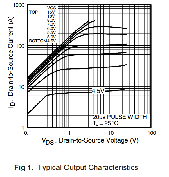
The IRF30205 looks good on the surface but you are only putting 4.7 volts on the gate. Figure 1 suggests the max current you can attain ~2 amp with a 0.1V drop. Its likely better that this but you will only get to the 0.008 ohms with 10V on the gate and the MosFet internal die at 25 °C.
I plan to swtich 5V Vin to ~9V (x2 18650 in series), so sence_signal pin definitely won't survive with that scheme. If i'll use voltage devider current will constantly flow + it could affect measurements accuracy, same with the Zener diode. What should I use? (+even bigger problem with item 3) ).
Use a divider with a total resistance of 10k - 20k. Add a 0.1µF cap at the input of the A/D.
Didn't quite figured out how to time analogwrite cos its working independently and I dont want to make PWM by software unless 100% nessesary. So just in case if i wont be able time it right i'm interested is it possible to take measurements despite Q2 work on PWM (there would be just a little bigger value spread)?
Looking forward to place 5 5W KNP-500 0.1Ohm in series or smth like that.
IRLB3034 then, but 3205 could stay if i'll figure out how not to burn SENCE with 9V.
Hmmm... i think i get it, 20kOhm right after R1 and 10k instead of R2 (there will be constant "leak" ~0.2mA), but I would like to avoid that, dont like realising this thing is always running, otherwise it is simplier to just throw away Q1 part. Did I get it right?
Close. I don't know your R1 resistance but your R2 = 10 ohms so I assume R1 is pretty low.
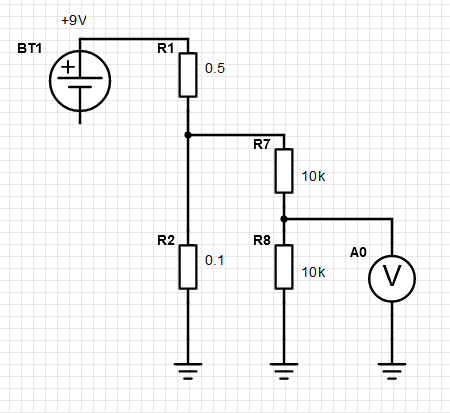
The 20k divider would be:
R7 in series with the Sense signal to the Arduino then R8 from the Arduino to ground. The divider could be as large as 100k.
Will the Arduino always be connected to +5v ? If so connect a .... 50k or so between the sense and the Arduino input. The parasitic loss would be (9 - 5)/50k = 80 µA
R1(probably stainless steel ~1k ppm) would go up to 300°C and I expect R2 not to go higher then 100°C.
But yea, I'll have to eather find high precision and high power resistors (unlikely) or find high precision and low power resistors and connect them in series or parallel (more likely some 1W smd) or use be best of what I can get (like KNP-500 (Al2O3) or something like it, they all have ~300ppm) and hope that they wont warm too much, cos measurin their resistance too will be too much.
I see no problem in R7 rating, maybe lower it and R8 to 10k (R1 won't be >1Ohm anyway), but... won't R7 affect R1-R2 devider ratios when Q1 opens?
1000ppm = 0.001Ohm/1°, +/-10° measurements on R1 is enough for me.
Not a chance, no space at all.
That can help a bit (switch Q2 to p-chanel and put it with R4&R6 before R1 + a bit different connection)
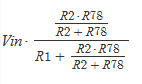
But even in the first scheme (with 5V Vin) should i take into account sence_signals (analog pin) resistance because it cosumes some current:
Vsence_signal = Vin (R2_general / (R1 + R2_general)) instead of simply calculating as Vsence_signal = Vin (R2 / (R1 + R2)), where R2_general = R2 * Rsence_signal / (R2 + Rsence_signal)?
The ones that i was able to find required min Vds of 4.5, when battery max is only 4.2V, so it would be possible to use them only with 9V (2x4.2V=8.4V to be presice).
UPD: and even then d-s current will be ~10A, which is low.
Impressive, but R1+10°C in my case would be 0.501, otherwise i had the same numbers. Now I understand how it all works and the weakest part is the components themselves (+/- 5% for resistors could influence measurements a lot, couldtn't find any precision ones available + they are low-power ones + couldn't find their TCR).
Any ideas how to improve accuracy other then measuring via arduino and comparing with the real values to calibrate calculations?
Metal film resistors (recommended over 5% carbon film) are usually 50 to 100 ppm.
I think you can get away with an R2 of 10 watts or so if I understand you plan correctly. Measuring the resistance of R1 will only take a few milliseconds not much time for heat to spread.