Is there voltage sensor or something similar that can measure AC voltages up to 200v at multiple frequencies? My main frequencies range is 20-80hz. I can use arduino or esp32 whatever is more suitable for it. Thanks
Yes.
Use a transformer and an opto coupler to measure the frequence using an Arduino.
1 Like
To measure the voltage safely, follow the instructions in this excellent site:
https://docs.openenergymonitor.org/electricity-monitoring/ctac/how-to-build-an-arduino-energy-monitor.html
I have ZMPT101B module that measure up to 250v ac but it is limited to 50 or 60hz frequency.. as soon I measure frequencies that are not 50 or 60hz measurment goes wild. So I want to measure voltage at different frequencies accurately.
If you don't need to measure frequency...
Assuming this is a "regular" AC sine wave, the peak voltage is 1.4 times the RMS.
Once you have a voltage that's "safe" (probably through a transformer) you can use a diode and capacitor, and the capacitor will charge-up to the peak.
That's a LOT easier than "sampling" a constantly-changing waveform... If you read AC you have to protect the Arduino from the negative voltage, then you have to find the peak, or calculate RMS, or calculate the average of the absolute values, etc. (The average of an AC waveform is zero.)
You'll probably need a voltage divider to further knock-down the voltage. And you need some kind of "load" across the capacitor so the DC voltage doesn't float.
You'll also need to add-back the ~0.7 drop across the diode.
.
1 Like
I dont need to measure and show frequency I just want accurate ac voltage reading at any frequency.
You have made that clear, several times.
Now, get serious, and define "accurate".
1 Like
Take a search engine of your choice and ask the WWW for 'Fourier analysis +arduimo' to collect some data to be sorted out to get the needed information.
The other side of your project is: Do you have a way of calibrating your Arduino device to match your accuracy requirements?
max -+ 1v accuracy
Yes I have multimeter
The method described on the OpenEnergyMonitor site will probably need to be calibrated to compensate for transformer inefficiency at the low and high end of that frequency range, and might not work at all at the extremes.
The best option is to buy a professional measuring instrument.
Hi, @movox
What is the application?
Why do you need this measurement?
Is it accurate from 20 to 80Hz?
Can you please tell us your electronics, programming, arduino, hardware experience?
Thanks.. Tom.. ![]()
![]()
![]()
![]()
I want to measure real time wattage that is coming from car amplifier.
I suppose so.
Started with everything few months ago.
How about current?
Or do you know the impedance of your speakers and cross over network at 20 to 80Hz?
Is this for horrendously loud sound system competition?
Thanks.. Tom.. ![]()
![]()
![]()
![]()
I got CT rated at 100A. I didn't tried it yet because voltage measurement was the first thing I started with.
Yeah it should measure up to 8-10kw rms.
In order to do the measurements you have listed, are you using a signal generator to produce a sine wave that feeds your amplifier? Do you also have an oscilloscope to verify the amplifier reproduces that sine wave with little or no distortion? And do you have a resistive dummy load for your amplifier that can handle that power during your test?
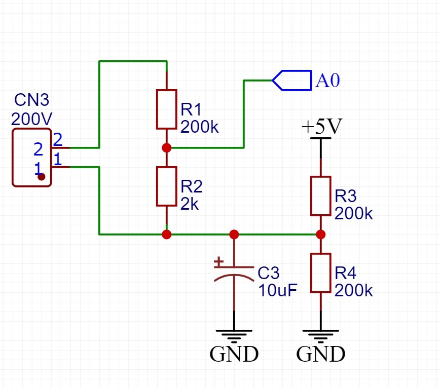
If this AC voltage comes for a car amplifier, and you can share amplifier ground with Arduino ground, then you don't need a transformer. Just use a 3-resistor voltage divider. Two of them actually, because car power amps work in bridge mode.
Leo..
I'm using pc as signal generator and I'm measuring voltage at speaker terminal.
Hmm. So I can use voltage divider to lower from 200v to 5v and use voltage offset to center it at 2.5v ?
Then you do not know how distorted the pc audio is and not close to a sine wave. For all your effort to pay off, you need to verify such things.