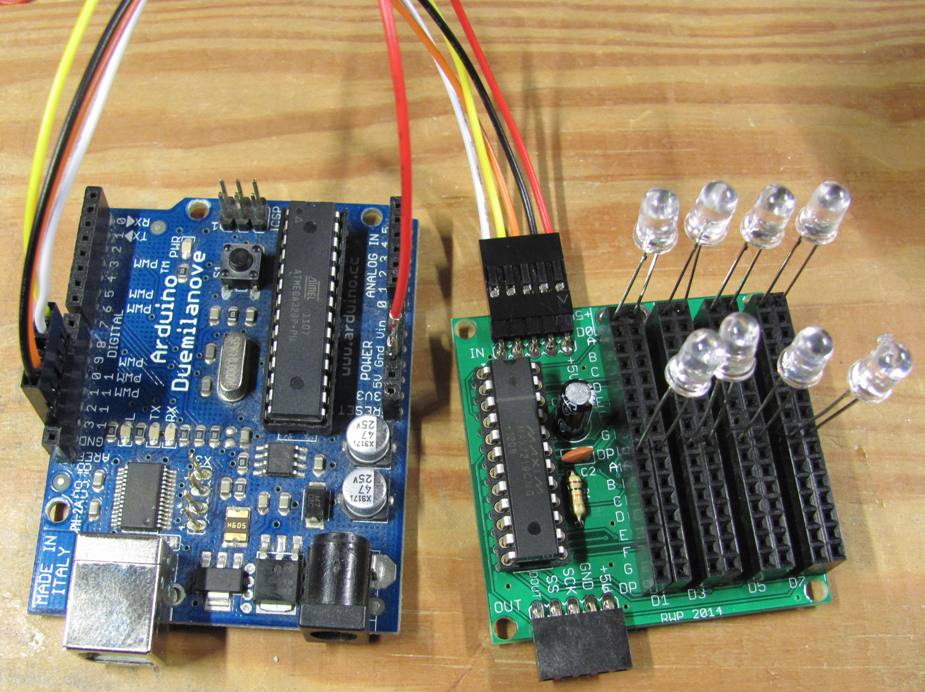
I'm new to Arduino so I decided to build a simple binary clock with LEDs--7 for Hours/Minutes and 7 for Mintues/Seconds with one extra flasher. Just having fun.
I used the following schematic. I was going to let it run overnight to see how accurate the milliseconds timer is, but my laptop sleeps when inactive which killed the USB power to the board. So I hooked up the 9v battery. In the morning the board was frozen and the barely used battery was drained. (My meter showed it as "questionable" at 6v.)
I was surprised, so I trying to work it out. 5v over a 330Ω resistor should be about 15mA. With an average of 6 LEDs illuminated that would be 90mA. The battery is rated at a little over 400mAh, it would drain in 4-5 hours so that seems plausible.
I was curious about other overhead (and I needed practice with the DMM), so started measuring current at various test points (on diagram). The current over the LED and resistor was only 7.2 mA, so the LED must be around 300Ω too. Current over just a resistor with no LED was 14.2mA, more like what I expected. At the Vcc for the shift register I saw 8-30 mA, depending on the number of LEDs illuminated, and at the return to Arduino GND 60-70mA. So maybe the battery lasted 6-7 hours instead of 4-5. Still not enough for overnight test.
I think my GND measurement only incudes the breadboard components, not the current used by Arduino itself. I'm not sure how I would measure that from the USB.
I also checked the return to GND from the shift register, but couldn't measure any. I was hoping to differentiate between current driving the output LEDs opposed to the current drawn by the register itself. Don't really understand why nothing would be measurable.
I haven't attempted this before, does my analysis sound reasonable?
And it looks like I'm in the market for a DC power supply besides just the USB!
Plug the USB lead of the Uno into a 5volt cellphone charger with USB socket.
Only 15 LEDs, so it should be possible to connect them all directly to the Uno, no 74HC595
(analogue pins are just digital pins with the added functionality of analogue-in)
As long as you keep total LED current below 200mA.
Leo..
but my laptop sleeps when inactive which killed the USB power to the board.
So is that a Windows one then? Because my Mac doesn’t do that.
You do not measure current across anything but through a point. The meter when in current mode looks like a short circuit, you need to break the circuit at the measuring point and join it back up with your meter.
Now you might be doing just that, but your words make it sound like you are using your meter like a volt meter to measure between two points but on current mode. Apologies if you are not doing that but you wouldn’t be the first beginner to make that mistake if you were.
Grumpy_Mike:
You do not measure current across anything but through a point. The meter when in current mode looks like a short circuit, you need to break the circuit at the measuring point and join it back up with your meter.
Yeah, I broke the circuit at the points indicated and connected the meter across the break. As I said, learning to make the DMM my friend.
Thanks for the tips on controlling and measuring USB power.
My setup has a max of 10 LEDs illuminated at any time, so I should be within the recommended 200mA draw for the Uno as a whole. If I were to change the design to use more LEDs or lights that draw more, would the correct approach be then to provide a separate power supply for the lights and control each with a transistor or relay?
With more lights, yes, add some kind of buffering.
Could be a MAX7219, can control 64 LEDs, selecting which are on or off is done with simple writes to its 8 internal shift registers. Even controls brightness so you just need 1 resistor for that.
Wire up the 8 LEDs or each bank as common cathode devices. All banks will have common anode lines, each bank will have its own common cathode line.
Or you can use a board like I offer that splits off 2 wires for each LED.
Or for fewer LEDs, just use two, three shift registers as needed. Change to TPIC6C595, shift register with 100mA current sink outputs. Wire +5 to LED anode, cathode to current limit resistor to shift register output. Shift in a 1, output goes low and turns on the LED.