HI!
I'm trying to create a midi controller with Arduino. my goal would be to create a mixer with 15 faders and 3 pots for each fader that works with Logic pro x. I managed to create a prototype with 1 fader and 3 knobs with both an Arduino Leonardo and a Pro Micro. Does anyone have any advice on how to get the 84 inputs I need? unfortunately I think that using multiplexer is not enough, should I use more than one board? Any advice is welcome!
p.s.
I also managed to understand how to make Arduino communicate with Logic, mine is really a hardware problem...
How do I fit all those inputs?
Welcome
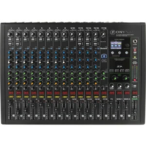
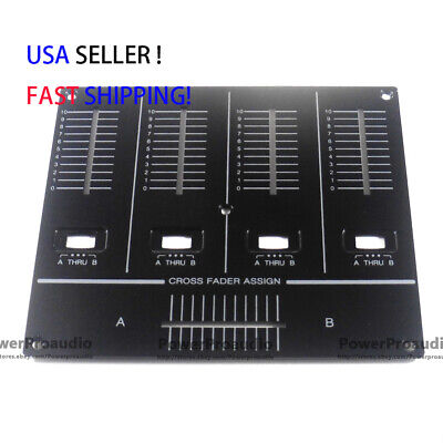
Is this what you are trying to build?
I got this complements of midi.org: "MIDI is a technical standard that describes a communication protocol, digital interface, and electrical connectors that connect a wide variety of electronic musical instruments, computers, and related audio devices for playing, editing, and recording music. A single MIDI cable can carry up to sixteen channels of MIDI data, each of which can be routed to a separate device."
Post your annotated schematic of your prototype and a block diagram of what you want. There are way to many loose ends to figure out.
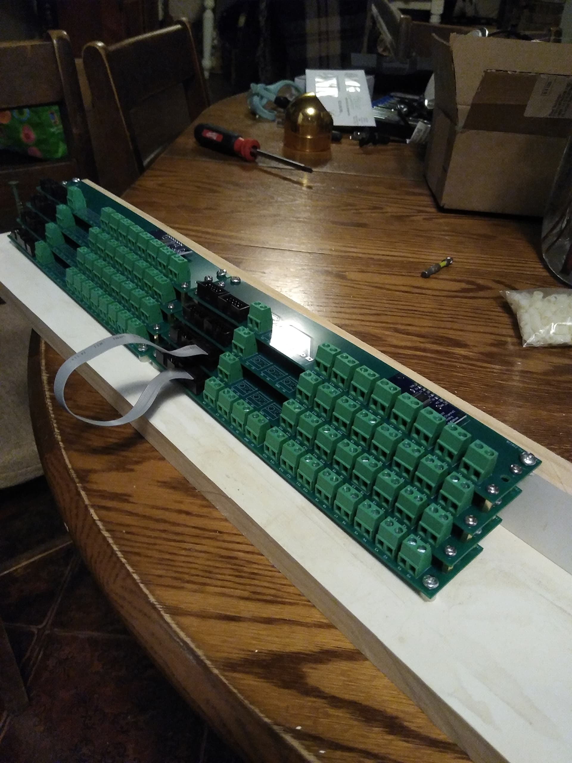
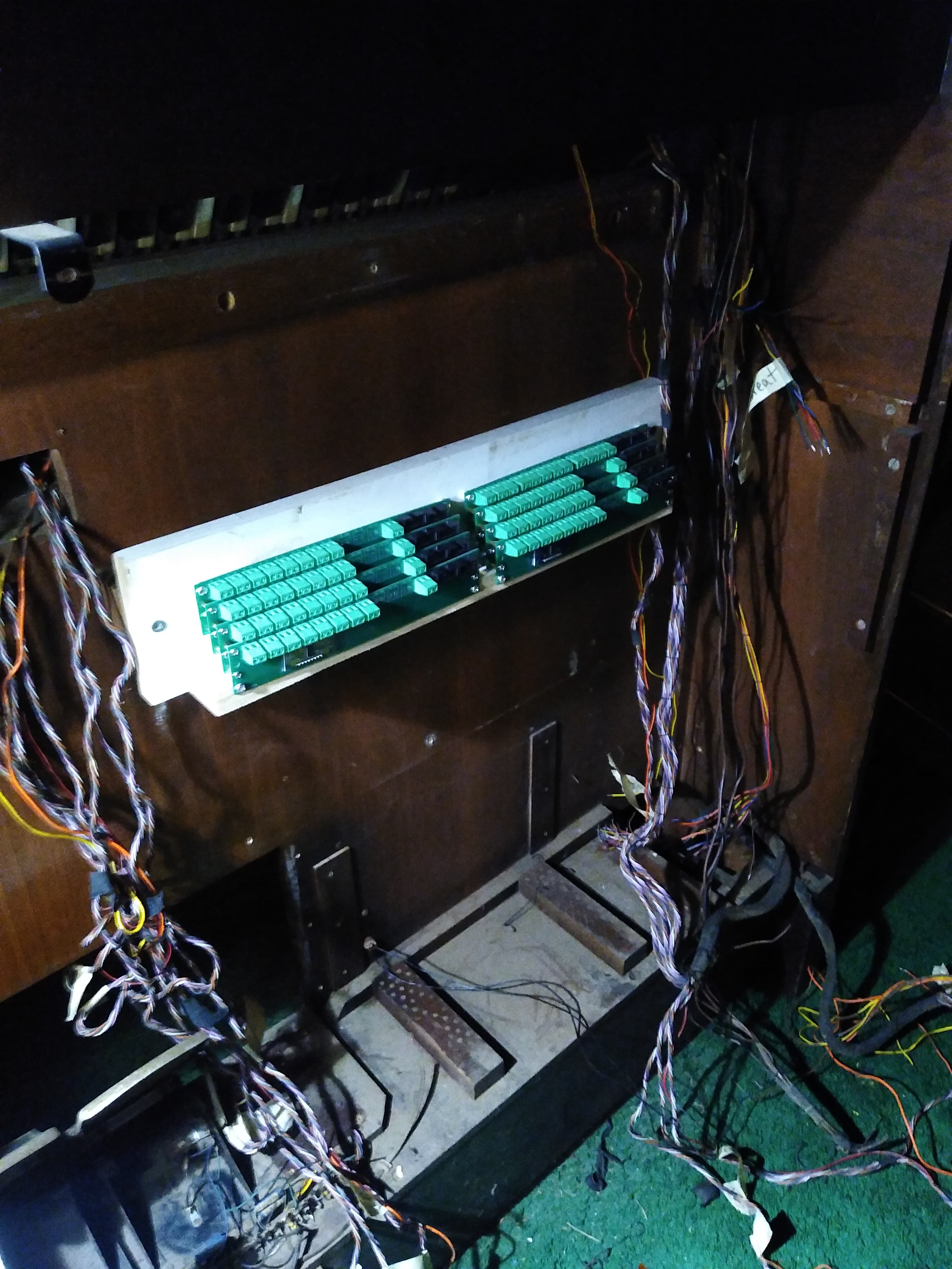
Hello ![]() I have recently been working on converting a church organ to MIDI, which required lots of inputs (about 230), so I made up a screw terminal board for 16 inputs. They can daisy chain together for more multiplexing
I have recently been working on converting a church organ to MIDI, which required lots of inputs (about 230), so I made up a screw terminal board for 16 inputs. They can daisy chain together for more multiplexing ![]() , I'm not sure it this will work for your space requirements, but maybe you will check it out and see what you think? I have extras for sale on tindie and eBay https://www.tindie.com/products/flow_state/multiplexer-screw-terminal-16-input-io-board/
, I'm not sure it this will work for your space requirements, but maybe you will check it out and see what you think? I have extras for sale on tindie and eBay https://www.tindie.com/products/flow_state/multiplexer-screw-terminal-16-input-io-board/

If you are making your own board you can use several multiplexers together to get the number of inputs you need
You could use multiple multiplexers on an I2C communication line so that all inputs can fit into one arduino
thank you sooooo much guys!
I'm going to respond you here.
@gilshultz here is what I'm trying to build

this is a part of the total mixer that I want to build.
there will be 15 fades and there will be 4 potentiometers for each fader.
I intend to add some buttons but I still have to understand if I will have enough inputs available!
regarding the annotated schematic you asked for, unfortunately I have to apologize because I don't have the knowledge to make one, I understand them in broad terms but I struggle to understand them completely.
in any case the prototype I created is composed of the following elements:
Arduino Leonardo
1 Fader
4 Knobs
I connected the power and ground of each element thanks to a Breadboard and the following components in this way to the Arduino.
A0 FADER
A1 KNOB 1
A2 KNOB 2
A3 KNOB 3
A4 KNOB 4
I hope I have been exhaustive, if you need further information just ask ![]()
@LanGenz unfortunately I don't have the skills to create a custom board, although I think that that would be the most efficient way and perhaps the least complicated in terms of hardware...
on the other hand, your screw terminal board also seems very interesting, if I gave you more information do you think you could tell me whether it should be used for my project? ![]()
Yeah, I will see if I can help you with your project. I think the screw terminals may be too bulky if you want all the electronics to be inside the mixer housing, but it could work with a taller housing. You would need 6 boards ( 5 x 16 for 80 inputs, and a 6th one to select between boards). For specs, what is the size and depth of the housing you are going for?
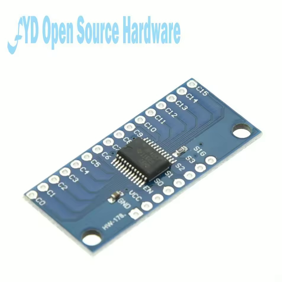
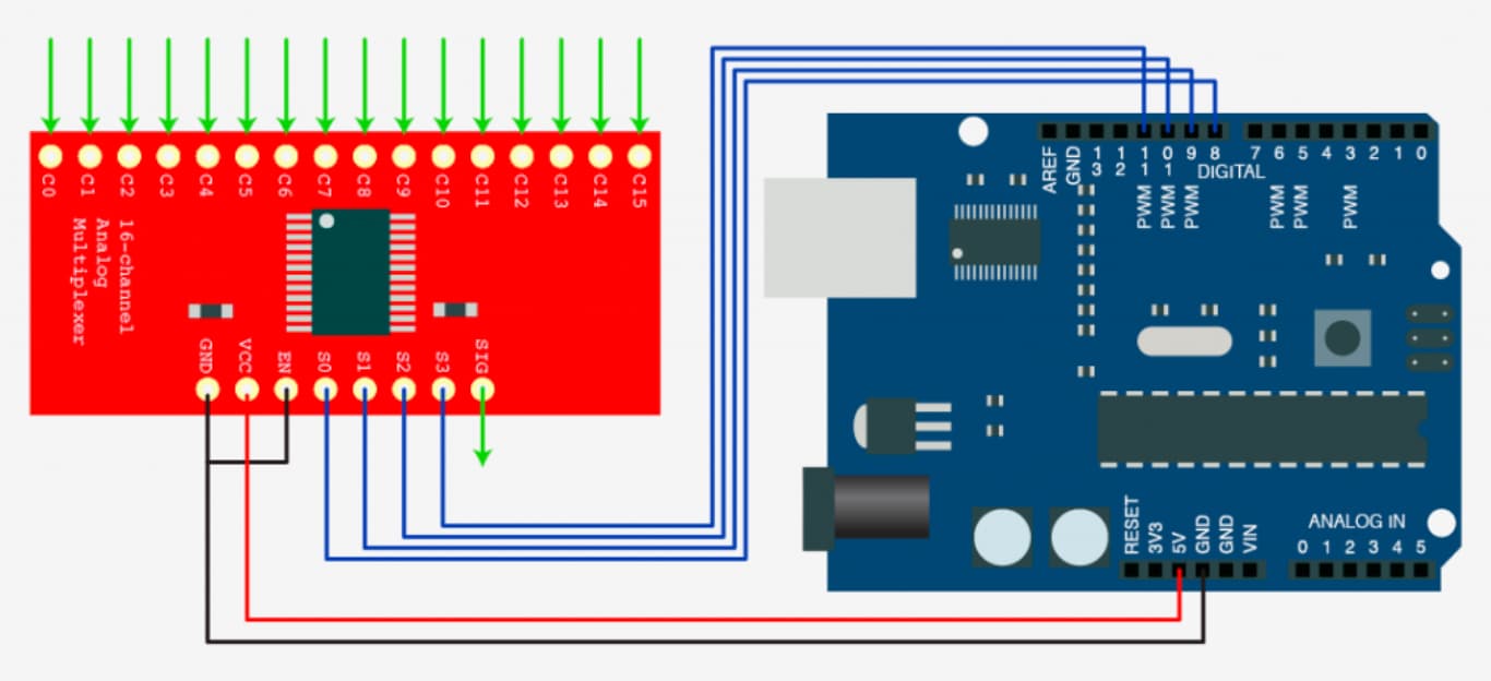
That is the same model that I use on my screw terminal board. If you use 5 multiplexers of this style, you can pass the control pins from one board to the next, and then use an enable pin for each multiplexer. This means you will use 4 control pins (S0,S1,S2,S3) and then 5 enable pins, and 1 signal pin. In total this will use 10 input pins on your leonardo to get the 80 inputs using the multiplexers.
thank you soooo much, I've managed to conncet all correctly but when I upload the code the Arduino spams values

This is the prototype with only one multiplexer and all 16 potentiometers.
This is the code
const int s0 = 4;

const int s1 = 5;

const int s2 = 6;

const int s3 = 7;

const int SIG_PIN = A0; // Pin analogico collegato all'uscita del multiplexer
int lastValues[16]; // Array per memorizzare gli ultimi valori letti
void setup() {

Serial.begin(115200);

pinMode(s0, OUTPUT);

pinMode(s1, OUTPUT);

pinMode(s2, OUTPUT);

pinMode(s3, OUTPUT);

for (int i = 0; i < 16; i++) {

lastValues[i] = -1; // Inizializza con un valore non valido

}

}
void loop() {

for (int i = 0; i < 16; i++) {

selectChannel(i);

delay(5); // Piccola attesa per la stabilizzazione del segnale

int value = analogRead(SIG_PIN);
    if (value != lastValues[i]) { // Solo se il valore cambia
        Serial.print("Potenziometro ");
        Serial.print(i);
        Serial.print(": ");
        Serial.println(value);
        lastValues[i] = value;
    }
}

}
void selectChannel(int channel) {

digitalWrite(s0, channel & 0x01);

digitalWrite(s1, channel & 0x02);

digitalWrite(s2, channel & 0x04);

digitalWrite(s3, channel & 0x08);

}
this is what the serial monitor gives me, even if I'm not touching the potentiometers
"
Potenziometro 5: 329
Potenziometro 6: 314
Potenziometro 7: 288
Potenziometro 8: 351
Potenziometro 9: 385
Potenziometro 10: 362
Potenziometro 11: 347
Potenziometro 12: 369
Potenziometro 13: 386
Potenziometro 14: 353
Potenziometro 15: 357
Potenziometro 0: 312
Potenziometro 2: 273
Potenziometro 3: 291
Potenziometro 4: 322
Potenziometro 5: 313
Potenziometro 6: 283
Potenziometro 7: 309
Potenziometro 8: 377
Potenziometro 9: 360
Potenziometro 10: 344
Potenziometro 11: 378
Potenziometro 12: 376
Potenziometro 13: 355
Potenziometro 14: 368
Potenziometro 15: 398
Potenziometro 0: 290
Potenziometro 1: 279
Potenziometro 2: 305
Potenziometro 3: 320
Potenziometro 4: 291
Potenziometro 5: 298
Potenziometro 6: 320
Potenziometro 7: 317
Potenziometro 8: 339
Potenziometro 9: 362
Potenziometro 10: 385
Potenziometro 11: 367
Potenziometro 12: 339
Potenziometro 13: 372
Potenziometro 14: 386
Potenziometro 15: 366
Potenziometro 0: 277
"
As you see it's spamming values.
I think it's a power problem, any suggestions?
Maybe your potentiometers aren't grounded correctly? It is hard for me to tell from this picture how you have them wired exactly. If you can verify that this wiring works with just one potentiometer, then with two, and see if you can find the problem. Maybe you have a bad jumper, maybe you aren't grounding the signal correctly, or maybe your 5v is not stable
unfortunately the problem still persist with only one potentiometer.
It's hard to tell from the picture, but in the bread board in the bottom left, the potentiometer on the far right, it looks like 5v is going to the far right pin, GND to the middle, and signal on the far left. Is this what I'm seeing? You should have the signal pin in the middle on the sweeper, and 5v and GND on either side.
you’re correct, signal is in the middle, sorry for the picture🥲