I bought a MIDI breakout box in combination with and Arduino Uno R3.
The Midi In and Midi Out work fine.
Unfortunately I could not find any technical documentation (the board
does not show any manufacturer or product name.
So I could not find a documentation. Most of all I would like to find out,
which pins are used by the MIDI functionality of the board,
and which are potentially free to use for additional functionality
(like status info or add more controls).
How can I find out, which pins are occupied and which are not?
ah you posted the pics at the same time I was posting mine
in an eBay filing I've seen this
Description:
Through the MIDI adapter plate, your Arduino board or other microcontrollers can be accessed to powerful MIDI communication protocol. MIDI protocol and asynchronous serial interface has many similarities, so users can use the micro-controller UART pin to send MIDI event information.
MIDI adapter plate provides MIDI - IN and MIDI - OUT connection, and MIDI THRU port. MIDI - port is light IN isolation, to prevent the ground loop. MIDI adapter plate can be installed directly like a shield at the top of the Arduino board: connect MIDI - IN/THRU to for Arduino hardware RX pin, connect MIDI - OUT to TX. It Arduino data and analog pin, power bus and the bus can transfer out.
The RUN/PGM switch can let users on the forArduino board serial port programming, without having to remove the board. Note: the three hole MIDI connector no welding on the MIDI adapter plate, but these connectors included in this product.
/*
MIDI note player

This sketch shows how to use the serial transmit pin (pin 1) to send MIDI note data.
If this circuit is connected to a MIDI synth, it will play
the notes F#-0 (0x1E) to F#-5 (0x5A) in sequence.

The circuit:
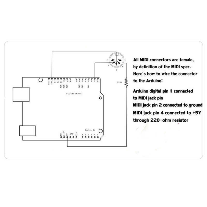
* digital in 1 connected to MIDI jack pin 5
* MIDI jack pin 2 connected to ground
* MIDI jack pin 4 connected to +5V through 220-ohm resistor
Attach a MIDI cable to the jack, then to a MIDI synth, and play music.
*/
void setup() {
// Set MIDI baud rate:
Serial.begin(31250);
}

void loop() {
// play notes from F#-0 (0x1E) to F#-5 (0x5A):
for (int note = 0x1E; note < 0x5A; note ++) {
//Note on channel 1 (0x90), some note value (note), middle velocity (0x45):
noteOn(0x90, note, 0x45);
delay(100);
//Note on channel 1 (0x90), some note value (note), silent velocity (0x00):
noteOn(0x90, note, 0x00);
delay(100);
}
}

// plays a MIDI note. Doesn't check to see that
// cmd is greater than 127, or that data values are less than 127:
void noteOn(int cmd, int pitch, int velocity) {
Serial.write(cmd);
Serial.write(pitch);
Serial.write(velocity);
}
MIDI IN connects to the Arduino’s RX pin (pin D0), allowing the Arduino to receive incoming MIDI data.
MIDI OUT connects to the Arduino’s TX pin (pin D1), allowing the Arduino to send MIDI data to other devices.
MIDI THRU passes the incoming MIDI data from MIDI IN to additional devices. Internally, the MIDI THRU port is likely connected to the MIDI IN port through a simple signal relay circuit ➜ the MIDI THRU essentially repeats the signal coming into the MIDI IN port, passing it along unchanged to the next device in the MIDI chain.
The following schematic is not of your board, but comes from the MIDI specifications.
These specifications can be found at midi.org/midi-1-0-core-specifications, but you need to be a member, and logged on to view them. (membership is free, you just have to register).
It is a typical schematic, so it is going to be similar to what is on your shield.
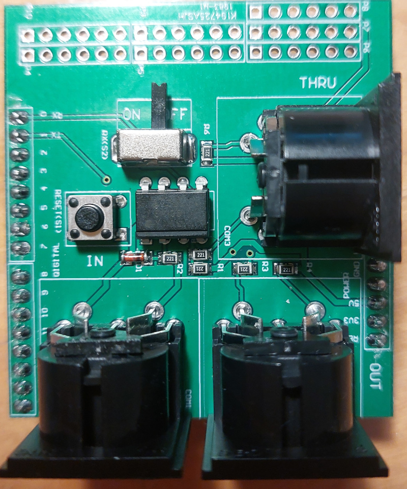
(For instance, I can see the 6 x 220Ω resistors, a diode and an opto-isolator on your shield.)
You will see that there are only two connections that go to the Arduino, they are labelled as 'TO UART' and 'FROM UART'.
They connect to the serial interface on pins 0 and 1.
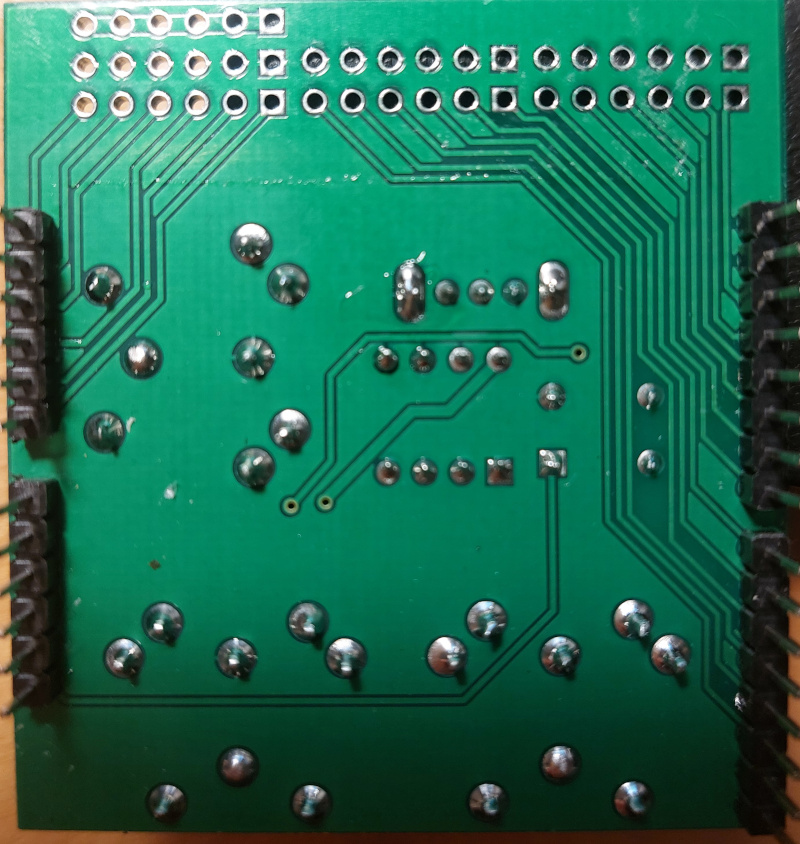
You can see tracks on your PCB going from pins 0 and 1 towards the opto-isolator.
The track from pin 0 goes to a switch, so that you can disconnect the MIDI circuit when uploading sketches to the shield.
So I will solder buttons and LEDs to the breakout-pins (upper right side in your picture)
to the other pins. Its great that this MIDI-board is expandable. Thanks again!
Yes, it looks as though all the unused digital pins connect to one row of 12 pins, with GND? available on the other row for connecting pushbuttons/switches.
The analog pins go to a row of 6 pins, and it looks as though GND and 5V go to the other two adjacent rows of 6 pins for connecting up to 6 potentiometers.
Yeah! in my application I will use one button to select a mode
and then I still seem to have 5 leds to display state information
about incoming and outgoing midi messages.
Thats more than I expected!