Minimum wiring of 2.4" tft display for touch screen functionality

Hello everyone,

I'm currently working on a ECG Simulator.

The project is to work in the following manner: The tft screen renders a logo, and asks the user to select a graph to show on the screen. However, there are two boards. ESP32 as a transmitting device that sends digital signal to a MCP4725 12 bit DAC that fowards an analog voltage to an Arduino Uno that reads through analogRead(A5) and plots it on the tft screen. My question is, instead of using the wifi functionality of the ESP32 in order to ask the user to select the graph. I'd like the user to touch on the screen on the desired option. Now, how do I know what's the bare minimum wiring on the tft-Uno interface so that the screen still works properly and I can use the other port of the Uno to feed signal to the ESP32 and select the graph from the stored data arrays.

Here is the schematic of the connections:

This project is a enhancement to this: MCP4725 DAC Read Analog Voltage Value with Arduino Uno - #5 by ec2021

Hi. It's not a schematic! It would be really helpful if you did post a schematic, because many of the components don't have their pins labelled, so the forum can't check for errors to help you.

Fritzing has a schematic view, so you can use that.

EDIT: Nontheless, I have spotted a wiring error. No common ground between the Uno and the breadboard.

Hi Paul, thanks for the reply.

I've drawn the schematic on Kicad as some of the components do not have symbols on Fritzing. I could not find a datasheet to the current screen I'm using. But on the store I bought it there this saying:

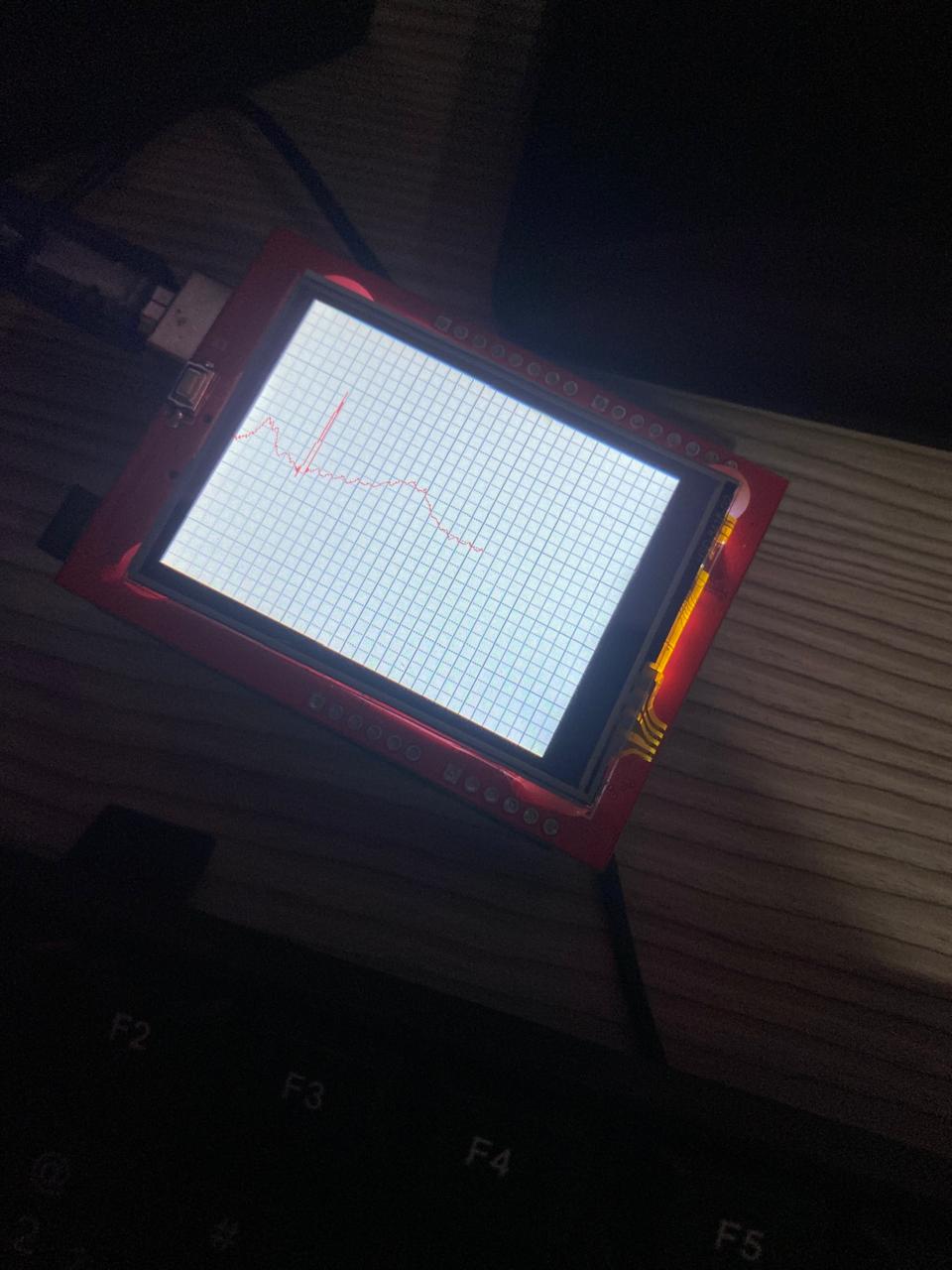
"This LCD Shield has a resolution of 240x320 pixels with individual control for each pixel. It also integrates a controller chip with video RAM, allowing you to use a driver to optimize its performance. It features 4 backlight LEDs and 18-bit color depth, offering 262,000 variations of colors and shades.

At the bottom of the Shield, there is a standard Micro SD card slot where data read by the LCD, digital photo albums, or any other application that requires expansion space for your project can be stored.

This Shield-shaped screen allows for quick and simple attachment to the Arduino without the need for wiring or soldering, making it ready for immediate use in applications that need to display information alongside the project, such as some type of menu where options are shown directly on the LCD in real-time. Another great application is when you need to interact with the project, such as in a password system, as the screen is touch-sensitive.

Specifications:

Screen size: 2.4 inches;
Micro SD card slot;
LCD color: 65K;
Resolution: 240 x 320;
Touch screen: 4-wire resistive touchscreen;
Interface: 8 data bits plus 4 control lines;
Operating voltage: 3.3-5V;
Visible screen dimensions (LxW): 50x39mm;
Shield dimensions (LxWxH): 72.3 x 52 x 7mm;
The Arduino pins used are: digital pins 5-13 and analog pins 0-3. This means you can use digital pins 2, 3, and analog pins 4 and 5. Pin 12 will be available if the SD card is not used.

Documentation:

Libraries"

The schematic is attached as pdf file.
ecg-sim-sch.pdf (41,3,KB)

Do you think it would be possible to program a LCD Crystal Display to do the same job as a the TFT screen but without the colours?

Thanks for pointing the common ground issue out, I'll fix it on the next build.

Thank you.

Have I understood your idea correctly? You want the user to select a graph on the TFT touch screen. The Uno will interpret the touch command and send a message to the ESP32. The ESP32 will then fetch the signal pattern from its memory and send that to the DAC which will turn this into an analog signal. The Uno will then use its ADC to turn that analog signal back into a digital signal and display it on the TFT?

Maybe I'm missing something, but that seems to me like a bizarrely over-complex solution. Why not remove the ESP32 and DAC completely? When the user selects a graph, have the Uno fetch the digitised signal from it's memory and directly display it on the TFT?

A TFT is a type of LCD display. You don't have to use colour if you don't want to, you can simply draw everything in black & white.

But I've never seen a monochrome display with a built-in touch screen, displays with touch screen all seem to be colour. Maybe they do exist but I guess they will be rare and expensive and won't have an Arduino library to make using them easy.

But how does changing the display help you to achieve your project?

Hi Paul,

So, I agree with you on the point that it's quite complex but the idea is for the ESP32 simulate a human heart and have two separate ends a transmitting board and a receiving board (that makes the role of a ECG machine). I'll do that later, but I plan to test some ECG boards I designed myself.

The thing about the LCD screen is that it's larger but I was not sure if it you be possible to show these kind of graphs with precision on it:

You perfectly understood the idea. I'm jotting down some code to test now that I realized that pins 0 and 1 are available to make that communication possible.

Do you have any advice before providing you with the code?

Not on Uno. They are used for uploading code to the Uno and debugging using the serial monitor.

Are any other pins available? For example, how did you discover that A5 was available? A shield usually "occupies" every pin on Uno but may not actually use them all.

Understanding this shield you have may be key to success of your project.

Studying your schematic again, I can see there are no other available Uno pins.

This TFT display, with it's 8-pin parallel interface, consumes almost every pin.

Other TFT displays use the SPI interface, which would require fewer Arduino pins and free up pins for other purposes. Could you find a TFT display shield like that?

This TFT shield uses SPI interface, so in theory many more Uno pins are "available".

In practice, how you get to access those unused pins is is another problem. This is the reason I avoid using and don't recommend Uno or shields! They seem convenient to beginners, but are very inflexible for anything more than simple demonstration projects.

I prefer using breadboards and breadboard-compatible Arduinos and other components for prototyping and final assembly and soldering onto stripboard/veroboard or custom PCB.

This topic was automatically closed 180 days after the last reply. New replies are no longer allowed.