I’m trying to use a gate level N-channel MOSFET as a switch to complete the negative side of a circuit to turn on a motor. The power to the DC motor is off because the negative wire is disconnected from the negative terminal of the battery, but when the Arduino puts the pin high (Gate), it connects completes the negative side of the circuit and turns the motor on for a moment.
When I attempt to wire the MOSFET (shown below) with the negative battery lead to the source, the motor negative lead to the drain, and the arduino pin the gate, the motor turns on no matter what-even when the gate isn't high. This means that the source and drain are somehow connected which I don't understand.
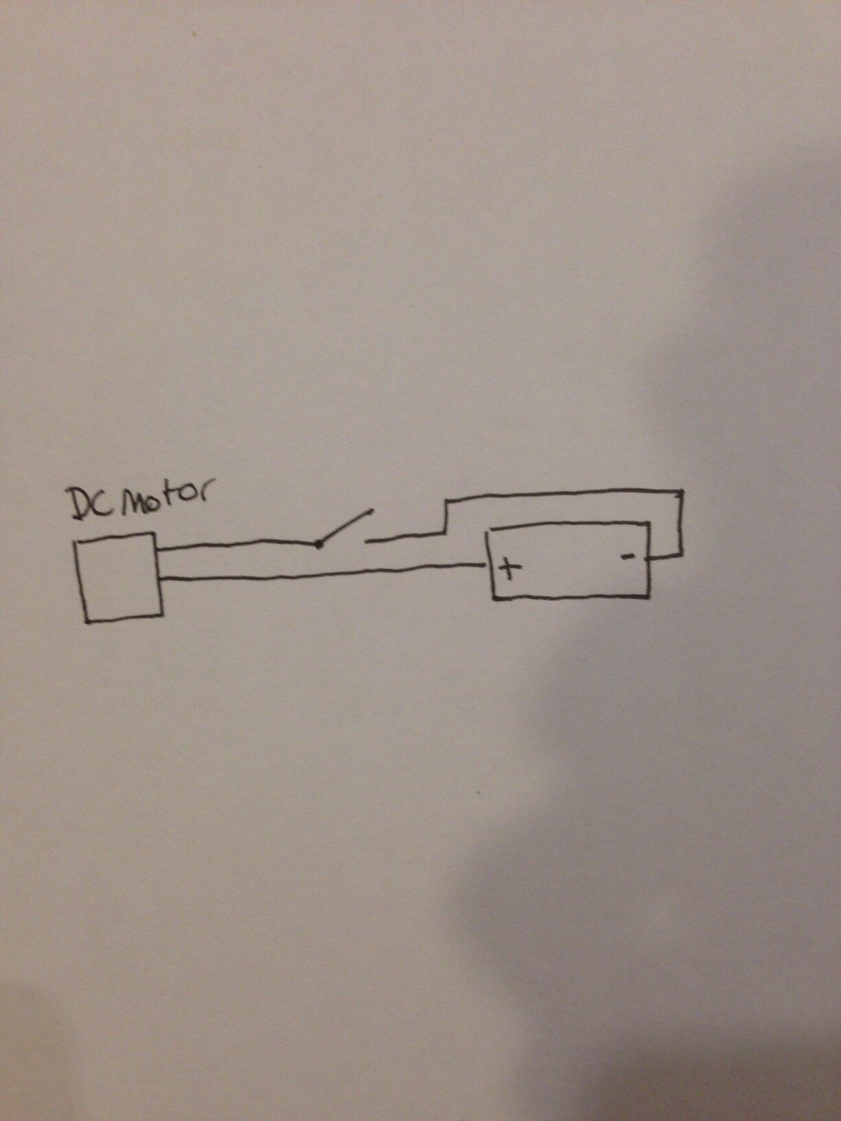
I have watched videos on MOSFETS and seem to understand how they work but still cannot get mine to work. I have a diagram of the general idea:
How I'm attempting to implement the MOSFET with my Arduino:
"You also need a resistor between the gate and ground"
Is this just a pull down resistor? Seems like this is a common method from what I read. Can I ask why a 1K, I'm used to using 10K pulldown/pullup resistors.
In my diagram I had the two negative leads attached to the gate and drain, but it looks like in the example jremington posted, the + is attached source to the and ground is attached to the drain.
tinman13kup:
You also need a resistor between the gate and ground, to ensure you pull the charge off the gate when the pin goes low. 1K should do it.
I think you got things a bit mixed up here.
An Arduino port can source AND sink, so a pull down resistor is not needed to pull the gate LOW.
The pull down resistor has another function.
It keeps the gate at ground potential during bootup, when the pin is still not configurated as output.
After that it's not needed, since the "pull down" of an Arduino pin is much stronger (~25ohm) than an external 10k or 1k resistor.
The pull down resistor should be on the Arduino pin side of the gate/pin current limiting resistor.
A pull down resistor on the gate side acts as a voltage divider, and lowers gate drive voltage.
See this page for the right ways to drive a mosfet with an Arduino pin.
What MOSFET are you using? MOSFETs are made with a wide range of current and voltage specifications, so we need to know exactly which one you are using.
freebird4446:
"You also need a resistor between the gate and ground"
Is this just a pull down resistor? Seems like this is a common method from what I read. Can I ask why a 1K, I'm used to using 10K pulldown/pullup resistors.
Doesn't need to be anything like 1k, 100k will work fine.
You haven't said anything about the nature of the load or its supply, please don't leave us in the dark, you might be doing something unwise without us knowing, like trying to switch very high power with PWM, in which that simple circuit is not adequate.