Hi,
I'm trying to do the following project replacing 28BYJ-48 Step motors for motors with encoder. But when I try to modify the pins to use my motors, doesn't work. Motors not spin.
Original project works with arduino UNO and my robot with arduino mega. I attached some extra info.
Thanks in advance!
#define SPEED 140 #define TURN_SPEED 160 #define speedPinR 9 // Front Wheel PWM pin connect Right MODEL-X ENA #define RightMotorDirPin1 22 //Front Right Motor direction pin 1 to Right MODEL-X IN1 (K1) #define RightMotorDirPin2 24 //Front Right Motor direction pin 2 to Right MODEL-X IN2 (K1) #define LeftMotorDirPin1 26 //Front Left Motor direction pin 1 to Right MODEL-X IN3 (K3) #define LeftMotorDirPin2 28 //Front Left Motor direction pin 2 to Right MODEL-X IN4 (K3) #define speedPinL 10 // Front Wheel PWM pin connect Right MODEL-X ENB
#define speedPinRB 11 // Rear Wheel PWM pin connect Left MODEL-X ENA #define RightMotorDirPin1B 5 //Rear Right Motor direction pin 1 to Left MODEL-X IN1 ( K1) #define RightMotorDirPin2B 6 //Rear Right Motor direction pin 2 to Left MODEL-X IN2 ( K1) #define LeftMotorDirPin1B 7 //Rear Left Motor direction pin 1 to Left MODEL-X IN3 (K3) #define LeftMotorDirPin2B 8 //Rear Left Motor direction pin 2 to Left MODEL-X IN4 (K3) #define speedPinLB 12 // Rear Wheel PWM pin connect Left MODEL-X ENB
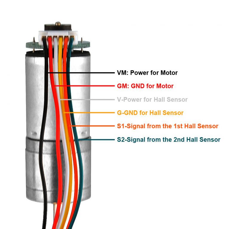
That original project uses 5V stepper motors. The picture you reference for your motor with encoder is just a DC motor but it doesn't say what voltage you need to supply to drive it. I would guess you can't do it at 5V and probably needs either 12V or 24V to do the job. You will need to find the specs on that motor. You will also need a better motor driver to handle the higher voltage
Like I stated in my previous reply, you need to get the specs on these new motors you wish to use. I bet they are not the 5V type. You could test them out by just directly connecting them to your 5V power supply and see if they rotate or not.
Hi,
Yes. Those motors includes a L298N driver for two motors and with the example code works fine. Moves, follow line, works with ultrasonic sensor, but I need to use with the code for the CNC Router, and replacing the pins for the motors, doesn't work.
Thanks
Then take the working example code and incorporate that into your CNC Router code. Going from a stepper motor to a DC motor is more than a matter of replacing pins. They operate differently
If you are making a CNC device then it will be very much simpler to use stepper motors. If the 28BYJ motors don't have the performance you need then just get more suitable stepper motors and stepper motor drivers.
You can buy very expensive industrial servo motors with their specialised controllers which behave like stepper motors but are actually DC motors with encoders. Making your own equivalent would be a huge challenge. And don't confuse these industrial servo motors with the cheap hobby servos used for model planes and boats.
The stepper motor code makes the motor move a certain number of steps, ending at the desired position.
Your DC motor + encoder code will have to tell the motor to move, then carefully keep track of the encoder to know how much the motor moved, and stop when the required distance has been moved (by number encoder pulses received). You may have to slow down the motor before reaching the end point to prevent overshoot. Then DC motors don't hold position as easily as steppers do (you'll have to use a worm drive), so if your X motor is at position and you switch off the power, it may move when the Y motor is moving the spindle.
It's not just because that CNC machines normally use stepper motors.