Multiple HC-SR04 with as few pins as possible

zhomeslice:
I have succeeded in triggering all at the same time using interrupts :slight_smile:

#define TriggerPin  2                  // output pin all trigger pins are linked to.

#define SamplesToAverage 1            // number of ping samples to average together for use
#define DelayBetweenPings 15            // delay after ping data is completely recieved all have reported in and the next trigger pulse in miliseconds (5 seems to be great)

unsigned long Timer, zTimer, xTimer; // Delay timers
volatile unsigned long SampleAge[20];
volatile int PinArray[20] = { -1, -1, -1, -1, -1, -1, -1, -1, -1, -1, -1, -1, -1, -1, -1, -1, -1, -1, -1, -1};            // List of pins that could be used as ping inputs:
unsigned long PingTime[20] ;
volatile int ToCompleteCtr;
volatile  unsigned long PingTimeX[20];
volatile  int PingSamplesX[20];
volatile  unsigned long edgeTime[20];
volatile  uint8_t PCintLast[3];
volatile  uint8_t mask[3];
int PinMask[3];
float Measurements[20] = {0, 0, 0, 0, 0, 0, 0, 0, 0, 0, 0, 0, 0, 0, 0, 0, 0, 0, 0, 0};
byte *MeasurementsB;

bool SerialEvent = false;                  // Detects serial imput  1
int I2CsendDataGo = 0;
uint8_t dataB[32] ;
int c, Pin;
int x = 0;
float inches, cm;
int DegSpread = 0;                 
static int SensorCount = 0;       
volatile byte PinList[25];

void setup() {

Serial.begin(115200);
  Serial.println("Send 1 for Readable Data, Send 0 For Interger Data");
  SensorCount = 0;
  pinMode(TriggerPin, OUTPUT);
  // enable interrupt for pin...
  // Select the pins you want to use for input
  // pciSetup(0); // Serial Communication
  // pciSetup(1); // Serial Communication
  // pciSetup(2); //This is my trigger pin
  pciSetup(3);
  pciSetup(4);
  pciSetup(5);
  pciSetup(6);
  pciSetup(7);
  pciSetup(8);
  pciSetup(9);
// pciSetup(10);
// pciSetup(11); // SPI communications
// pciSetup(12); // SPI communications
// pciSetup(13); // SPI communications
// pciSetup(14); // A0
// pciSetup(15); // A1
// pciSetup(16); // A2
// pciSetup(17); // A3
// pciSetup(18); // A4  i2c Communication
// pciSetup(19); // A5  i2c Communication
// pciSetup(20); // A6  for some clones
// pciSetup(21); // A7  for some clones

}

void loop() {
  Timer = millis(); // timing events!
  PingIt(); // Manage ping data
  if (SerialEvent) SendSerialData();
}

void RadarOut( int Degrees) {
  static int x = 0;
  static bool xz = true;
  static byte Sensor = 0;
  int deg = Degrees / SensorCount;
  Sensor = 0;
  while (Sensor < SensorCount) {
    if (Degrees > 0) {
      Serial.print((Sensor * deg) );
      if (Degrees != SensorCount) {
        Serial.print("*");
      }
      Serial.print("=");

} else {
      Serial.print("Pin#");
      Serial.print(PinList[Sensor]);
      Serial.print("=");

}

Serial.print(Measurements[Sensor]);
    Serial.print("cm ");
    Sensor++;
  }
}

void PingTrigger(int Pin) {
  digitalWrite(Pin, LOW);
  delayMicroseconds(1);
  digitalWrite(Pin, HIGH); // Trigger another pulse
  delayMicroseconds(5);
  digitalWrite(Pin, LOW);
}

bool AllClear() {
  return (!(PinMask[0] & PIND) && !(PinMask[1] & PINB) && !(PinMask[2] & PINC) && !ToCompleteCtr); //  all the input pins are LOW
}

void PingIt() {
  static int SampleCt = 0;
  static bool DelayLatch = true;
  if ( AllClear()) { // Wait
    if (DelayLatch) {
      xTimer = Timer + DelayBetweenPings;
      DelayLatch = false;
    }
    if ((Timer - xTimer) >= 0 ) {
      for (int i = 0; i < 20; i++) {
      if (SampleCt >= SamplesToAverage) {
        byte Sensor = 0;
       
          // Serial.print(i);
          if ((PinArray[i] != -1) ) {
            //Serial.println("");
          //  Serial.println(PingTimeX[i]);
            if (PingSamplesX[i] > 0) {
             
            //  Serial.println(PingSamplesX[i]);
            //  Serial.println("\t");
            //  Serial.println(PingTimeX[i]);
              PingTime[i] =  (unsigned long) (PingTimeX[i] / PingSamplesX[i]); // average
              Measurements[Sensor] = (float) (microsecondsToCentimeters(PingTime[i]));
            }
            PingTimeX[i] = 0;
            PingSamplesX[i] = 0;
            Sensor++;
          }
        }
        SampleCt = 0;
        SampleAge[i] = micros();
      }

DelayLatch = true;
      SampleCt++;
      PingTrigger(TriggerPin); // Send another ping
      zTimer = Timer;
    }
  }
}

float microsecondsToInches(long microseconds)
{
  return (float) microseconds / 74 / 2;
}

float microsecondsToCentimeters(long microseconds)
{
  return (float)microseconds / 29 / 2;
}

void SendSerialData()
{
  SerialEvent = false;
  int val = Serial.read() - '0';
  while (Serial.available())Serial.read();
  if (val == 0) {
    DataMessage();
    Serial.write(dataB, 30); // respond with message
  } else  if (val == 1) {
    RadarOut( DegSpread);
    Serial.println();
  }
}

uint8_t DataMessage() {
  int x = 0;
  for (int i = 0; i < 15; i++ ) {
    dataB[x] = (uint8_t)(((uint8_t)Measurements[i]) >> 8);
    x++;
    dataB[x] = (uint8_t)Measurements[i];
    x++;
  }
}

// port change Interrupt
ISR(PCINT0_vect) { //this ISR pins 8~13
  static uint8_t pin;
  static unsigned long cTime;
  cTime = micros();        // micros() return a uint32_t
  pin = PINB; //  get the state of all pins bit 0 = pin 8, bit 1 = pin 9 dtc.
  ToCompleteCtr++;
  sei();                    // re enable other interrupts
  CheckTimers(8, 13,  1, pin, cTime);
}

ISR(PCINT1_vect) { //this ISR s A0~A5
  static uint8_t pin;
  static unsigned long cTime;
  cTime = micros();        // micros() return a uint32_t
  pin = PINC; //  get the state of all pins bit 0 = pin 8, bit 1 = pin 9 dtc.
  ToCompleteCtr++;
  sei();                    // re enable other interrupts
  CheckTimers(14, 19,  2, pin, cTime);
}

ISR(PCINT2_vect) { //this ISR pins 0-7
  static uint8_t pin;
  static unsigned long cTime;
  cTime = micros();        // micros() return a uint32_t
  pin = PIND; //  get the state of all pins bit 0 = pin 8, bit 1 = pin 9 dtc.
  ToCompleteCtr++;
  sei();                    // re enable other interrupts
  CheckTimers(0, 7,  0, pin, cTime);
}

void CheckTimers(uint8_t StartPin, uint8_t EndPin, uint8_t group, uint8_t  pin, unsigned long cTime )
{
  volatile uint16_t dTime;
  mask[group] = pin ^ PCintLast[group];
  PCintLast[group] = pin;       
  for (uint8_t ii = 0; ii <= (EndPin - StartPin); ii++) {
    if (mask[group] >> ii & 1) { // pin has changed
      if ((pin >> ii & 1))edgeTime[(ii + StartPin)] = cTime;
      else { // Pulse Went low calculate the duratoin
        dTime = cTime - edgeTime[(ii + StartPin)]; // Calculate the change in time
        PingTimeX[(ii + StartPin)] = PingTimeX[(ii + StartPin)] + dTime;
        PingSamplesX[(ii + StartPin)]++;
      }
    }
  }
  ToCompleteCtr--;  //when all interupts are complete this will return to zero
}

// Install Pin change interrupt for a pin, can be called multiple times
void pciSetup(byte pin)
{
  if (pin <= 7)PinMask[0] =  bitWrite(PinMask[0], pin, 1); // PIND for pins 0~7
  else if (pin > 13) PinMask[2] =  bitWrite(PinMask[2] , pin - 14, 1); // PINC for A0~A5 Starts on Pin 14
  else PinMask[1] =  bitWrite(PinMask[1] , pin - 8, 1); // PINB for pins 8~13
  pinMode(pin, INPUT);// enable interrupt for pin...
  *digitalPinToPCMSK(pin) |= bit (digitalPinToPCMSKbit(pin));  // enable pin
  PCIFR  |= bit (digitalPinToPCICRbit(pin)); // clear any outstanding interrupt
  PCICR  |= bit (digitalPinToPCICRbit(pin)); // enable interrupt for the group
  PinArray[pin] = 1;
  PinList[SensorCount] = pin;
  SensorCount++;
}

void serialEvent() {
  SerialEvent = true;
}


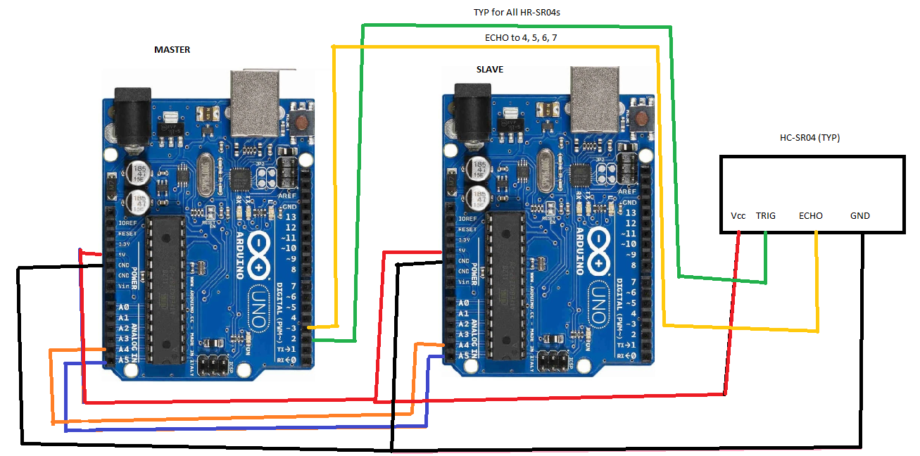
this is my setup 
each echo pin goes to a unique input and pin 2 is tied to all trigger pins 
all triggers activate at once

![Ping360.jpg|800x482](upload://3FcCNLqPKRgMJozU6Sav1S4lZw2.jpg)

my code can handle multiple pin changes at the same time and log the start time. when each echo pin restores the interrupts trigger again and store the end time giving the trip distance.
amazingly accurate. my setup uses 8 sensors I can't see why you couldn't use more you can attach to any pin including analog for example if you want to use analog pin 3 unremark: pciSetup(17); // A3

data is stored in an array available for you to access at will. and this is a non blocking script so other code can run at the same time.

Hello there!

By chance, do you have the same code for an Arduino Uno(atmega328p) ?? I'm having trouble looking at the registers and functionalities of each pins.

Thanks in advance!

fcastellaro:
Hello there!

By change, do you have the same code for an Arduino Uno(atmega328p) ?? I'm having trouble looking at the registers and functionalities of each pins.

Thanks in advance!

That is an atmega328 clone in the picture or a small UNO :slight_smile: This code is developed for the uno.
Z

zhomeslice:
That is an atmega328 clone in the picture or a small UNO :slight_smile: This code is developed for the uno.
Z

Thanks for the response.

Do you know if any pin of the atmega328 can work or be attached to an interrupt? Because i've tried your code with my configuration but the response are all zeros (previously i've done a more crude code on my own and it worked fine, so the wiring is not the problem).

Here is the only configuration I changed:

#define TriggerPin A5
pciSetup(3); //PIN_USS5
pciSetup(5); // PIN_USS2
pciSetup(8); // PIN_USS3
pciSetup(12); //PIN_USS4
pciSetup(A2); //PIN_USS1

Currently i'm trying to figure out a more "simple" (or at least more familiar) way to get this to work using the same aproximation of interrupts by the attachInterrupt() function, but as expected only the pin 3 worked. For this last result is that i asked you the question above.

Any help that you can give is more than welcome.

Thanks!

The attachInterrupt() function is for the so-called external interrupt which is pin 2 and 3 only.

The code above uses pin change interrupts, which are available on all digital inputs (i.e. pins 0-13 and A0-A5). Those work per port (PARTA, PORTB and PORTD each share an interrupt) so if you change pins you may have to change the code to look for the correct interrupt.

fcastellaro:
Thanks for the response.

Do you know if any pin of the atmega328 can work or be attached to an interrupt? Because i've tried your code with my configuration but the response are all zeros (previously i've done a more crude code on my own and it worked fine, so the wiring is not the problem).

Here is the only configuration I changed:

#define TriggerPin A5
pciSetup(3); //PIN_USS5
pciSetup(5); // PIN_USS2
pciSetup(8); // PIN_USS3
pciSetup(12); //PIN_USS4
pciSetup(A2); //PIN_USS1

Currently i'm trying to figure out a more "simple" (or at least more familiar) way to get this to work using the same aproximation of interrupts by the attachInterrupt() function, but as expected only the pin 3 worked. For this last result is that i asked you the question above.

Any help that you can give is more than welcome.

Thanks!

if you want more than 2 interrupts you must use this trick which is much more complex than attachinterrupt()
here is what i do
To enable an interrupt on a pin or pins add one or more of these lines into your code each enable an interrupt on this associated pin

    // enable interrupt for pin...
  // Select the pins you want to use for input
  // pciSetup(0); // Serial Communication
  // pciSetup(1); // Serial Communication
  // pciSetup(2); //This is my trigger pin
  pciSetup(3);
  pciSetup(4);
  pciSetup(5);
  pciSetup(6);
  pciSetup(7);
  pciSetup(8);
  pciSetup(9);
 // pciSetup(10);
 // pciSetup(11); // SPI communications
 // pciSetup(12); // SPI communications
 // pciSetup(13); // SPI communications
 // pciSetup(14); // A0
 // pciSetup(15); // A1
 // pciSetup(16); // A2
 // pciSetup(17); // A3
 // pciSetup(18); // A4  i2c Communication
 // pciSetup(19); // A5  i2c Communication
 // pciSetup(20); // A6  for some clones
 // pciSetup(21); // A7  for some clones

in the above example, I have pins 3 through 9 enabled for interrupts
inside the loop

void loop() {
 Timer = millis(); // timing events!
 PingIt(); // Manage ping data
 if (SerialEvent) SendSerialData();
}

PingIt() does all the work here. It calculates the distance from the travel time that the interrupts provide and displays it for us to use. after it reads the results that have returned from the interrupts it then triggers another ping as soon as all is clear.

now for the fun part

The hard work is done by the following interrupt ISR's

what happens when any pin is changed that we have enabled:
0~7 changed that we have enabled an interrupt for the following function is triggered.

ISR(PCINT2_vect) { //this ISR pins 0-7
// Code here
}

8~13

ISR(PCINT0_vect) { //this ISR pins 8~13
// Code here
}

and A0~A5

ISR(PCINT1_vect) { //this ISR s A0~A5
// Code here
}

during each interrupt, I quickly gather some information and free up the interrupts to catch more

static uint8_t pin;
static unsigned long cTime;
cTime = micros();         // Get the Interrupt time
pin = PINB; //  get the state of all pins bit 0 throu 7 or associated 8 pins
ToCompleteCtr++; trigger a change detection
sei();                    // re enable other interrupts
CheckTimers(8, 13,  1, pin, cTime);

CheckTimers() function goes through each pin and compares it to the last gather pin states to see what pin has changed High or low and assigns a start time or calculates the DeltaT of the travel time of only the pins that have changed during this interrupt to calculate the duration of the ping echo. this stores it in PingTimeX array for us to use in the pingIt() function when we are ready to deal with the captured data.

// port change Interrupt
ISR(PCINT0_vect) { //this ISR pins 8~13
 static uint8_t pin;
 static unsigned long cTime;
 cTime = micros();         // micros() return a uint32_t
 pin = PINB; //  get the state of all pins bit 0 = pin 8, bit 1 = pin 9 dtc.
 ToCompleteCtr++;
 sei();                    // re enable other interrupts
 CheckTimers(8, 13,  1, pin, cTime);
}

ISR(PCINT1_vect) { //this ISR s A0~A5
 static uint8_t pin;
 static unsigned long cTime;
 cTime = micros();         // micros() return a uint32_t
 pin = PINC; //  get the state of all pins bit 0 = pin 8, bit 1 = pin 9 dtc.
 ToCompleteCtr++;
 sei();                    // re enable other interrupts
 CheckTimers(14, 19,  2, pin, cTime);
}

ISR(PCINT2_vect) { //this ISR pins 0-7
 static uint8_t pin;
 static unsigned long cTime;
 cTime = micros();         // micros() return a uint32_t
 pin = PIND; //  get the state of all pins bit 0 = pin 8, bit 1 = pin 9 dtc.
 ToCompleteCtr++;
 sei();                    // re enable other interrupts
 CheckTimers(0, 7,  0, pin, cTime);
}

void CheckTimers(uint8_t StartPin, uint8_t EndPin, uint8_t group, uint8_t  pin, unsigned long cTime )
{
 volatile uint16_t dTime;
 mask[group] = pin ^ PCintLast[group];
 PCintLast[group] = pin;       
 for (uint8_t ii = 0; ii <= (EndPin - StartPin); ii++) {
   if (mask[group] >> ii & 1) { // pin has changed
     if ((pin >> ii & 1))edgeTime[(ii + StartPin)] = cTime;
     else { // Pulse Went low calculate the duratoin
       dTime = cTime - edgeTime[(ii + StartPin)]; // Calculate the change in time
       PingTimeX[(ii + StartPin)] = PingTimeX[(ii + StartPin)] + dTime;
       PingSamplesX[(ii + StartPin)]++;
     }
   }
 }
 ToCompleteCtr--;  //when all interupts are complete this will return to zero
}

The following function sets up the pin to be used as an interrupt and preps space for each interrupts to be easily accessible in an array

// Install Pin change interrupt for a pin, can be called multiple times
void pciSetup(byte pin)
{
 if (pin <= 7)PinMask[0] =  bitWrite(PinMask[0], pin, 1); // PIND for pins 0~7
 else if (pin > 13) PinMask[2] =  bitWrite(PinMask[2] , pin - 14, 1); // PINC for A0~A5 Starts on Pin 14
 else PinMask[1] =  bitWrite(PinMask[1] , pin - 8, 1); // PINB for pins 8~13
 pinMode(pin, INPUT);// enable interrupt for pin...
 *digitalPinToPCMSK(pin) |= bit (digitalPinToPCMSKbit(pin));  // enable pin
 PCIFR  |= bit (digitalPinToPCICRbit(pin)); // clear any outstanding interrupt
 PCICR  |= bit (digitalPinToPCICRbit(pin)); // enable interrupt for the group
 PinArray[pin] = 1;
 PinList[SensorCount] = pin;
 SensorCount++;
}

Hope this helps
Z

I finally understand how this is working. I am able to replicate the ping all at once with results that will display on the monitor, but then when i read it, I get a bunch of mess of unchanging values.

I started by building something similar without results, so then I tried the included code for pinging all at once and the reading. That didn't work so I tested out the wire library examples and it was able to write from one board to a second. Once I verified that, I went back to testing the code.

Below is what I get, any advice?

14:40:28.602 -> 35251 23487 55049 63822 52596 12851 13618 53 366 12849 54 41 46502 16383

bjde0b:
I finally understand how this is working. I am able to replicate the ping all at once with results that will display on the monitor, but then when i read it, I get a bunch of mess of unchanging values.

I started by building something similar without results, so then I tried the included code for pinging all at once and the reading. That didn't work so I tested out the wire library examples and it was able to write from one board to a second. Once I verified that, I went back to testing the code.

Below is what I get, any advice?

14:40:28.602 -> 35251 23487 55049 63822 52596 12851 13618 53 366 12849 54 41 46502 16383

did you send a Zero or a one through the serial port.

void SendSerialData()
{
  SerialEvent = false;
  int val = Serial.read() - '0';
  while (Serial.available())Serial.read();
  if (val == 0) {
    DataMessage();
    Serial.write(dataB, 30); // respond with message
  } else  if (val == 1) {
    RadarOut( DegSpread);
    Serial.println();
  }
}

now sending 0 you get a raw chunk of data you need to resend 0 to get the latest reading.

uint8_t DataMessage() {
  int x = 0;
  for (int i = 0; i < 15; i++ ) {
    dataB[x] = (uint8_t)(((uint8_t)Measurements[i]) >> 8);
    x++;
    dataB[x] = (uint8_t)Measurements[i];
    x++;
  }
}}

sending 1 gives you a radar type reading where each sensor is set across a number of degrees
for simplicity, if you have 8 sensors set the int Degrees to 0 and each sensor will be numbered 1 for sensor 1 2 for 2 and so forth
the readings will be in centimeters rather than times.
you need to resend a 1 each time you want a reading.

void RadarOut( int Degrees) {
  static int x = 0;
  static bool xz = true;
  static byte Sensor = 0;
  int deg = Degrees / SensorCount;
  Sensor = 0;
  while (Sensor < SensorCount) {
    if (Degrees > 0) {
      Serial.print((Sensor * deg) );
      if (Degrees != SensorCount) {
        Serial.print("*");
      }
      Serial.print("=");

    } else {
      Serial.print("Pin#");
      Serial.print(PinList[Sensor]);
      Serial.print("=");

    }

    Serial.print(Measurements[Sensor]);
    Serial.print("cm ");
    Sensor++;
  }
}

Z

I guess I am slightly different in running four sensors instead of eight. I blocked out the proper pins and then adjusted the code to show only four.

I get the proper readings with serial attached to the Slave which is pinging, but then when I attach serial to master, it just goes wacky.

Thanks Z for the help.

I have attached the master and slave. The slave gives the proper readings, but the master gives the anomalies. I tried changing the array from 16 to 4, but it didn't work either way.

master_reader_for_UltrasonicPingAllAtOnceI2C.ino (1 KB)

UltrasoundPingAllAtOnceI2CxSerial.ino (8.03 KB)

bjde0b:
I guess I am slightly different in running four sensors instead of eight. I blocked out the proper pins and then adjusted the code to show only four.

I get the proper readings with serial attached to the Slave which is pinging, but then when I attach serial to master, it just goes wacky.

Thanks Z for the help.

I have attached the master and slave. The slave gives the proper readings, but the master gives the anomalies. I tried changing the array from 16 to 4, but it didn't work either way.

So your question pertains to the communication between the array Arduino and Master Arduino. we are looking at sending the data retrieved by your HC-sr04 array over I2c bus from one Arduino to another. so first, you must have that i2c bus wired correctly Please send me a wiring diagram of your i2c connections.
Z

Okay, so I have attached a very poor drawing. Interesting, when I have GND in slave plugged in, serial display from SLAVE_PING goes dead and when I unplug it, it works again. Still not reading anything good by the MASTER. I have been studying IC2 and have been thinking about different ways to write and read for testing.

Slave_Pinger.ino (8.31 KB)

Master_Reader.ino (1.01 KB)

bjde0b:
Okay, so I have attached a very poor drawing. Interesting, when I have GND in slave plugged in, serial display from SLAVE_PING goes dead and when I unplug it, it works again. Still not reading anything good by the MASTER. I have been studying IC2 and have been thinking about different ways to write and read for testing.

You are missing pull up resistors on your i2c bus 2k ~ 4.4K ohm resistors work great connect one from data to positive and a second from clock to positive. Add these to your schematics so I can see you got it right. sorry I can't make the changes show you. I'm using my cell phone to help you.

I have seen these, didn't know why they were needed so I didn't have them.

I have added the 2k pull up resistors as per the attached drawing. I didn't change the two prior sketches I uploaded, but I still get bad return on monitoring the master. Slave monitor is still okay.

bjde0b:
I have seen these, didn't know why they were needed so I didn't have them.

I have added the 2k pull up resistors as per the attached drawing. I didn't change the two prior sketches I uploaded, but I still get bad return on monitoring the master. Slave monitor is still okay.

Something is not correct. The last time I messed with this project I had no trouble getting the communication to work. with this said I did simplify and clean up my messy code before posting it on this forum. This could have caused an error to appear that I missed.
While this post is about the HC-sr04 your questions are focusing on i2c communication.

You may want to debug using the most basic wire libraries. These are what I used to get the data across

The master reader is almost identical to my master reader the only difference is I am using 16 bit instead of 8 bit.
Try to get these examples to work.
Z

hello my friend, i have a problem i would be glad if you can help. I have to trigger and read echo only 3 my hcsr04 users. I closed the triggers with the help of tape. Will it work if I set up your setup? do you have any idea ?