I have built a PCB with an ESP32 and a BSS138 MOSFET.
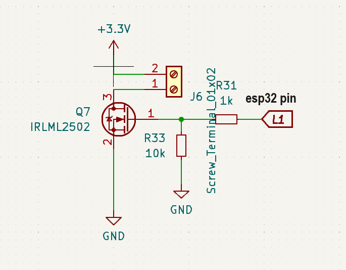
I want to control a device, (let say an LED), connected to a Terminal block. The Terminal block has two pins: one for 3.3V and the other for GND, which I want to control (On/Off) using the MOSFET.
I want to activate the GND pin in either of the following two ways:
If IO14 (M3) on the ESP32 is set to HIGH.
If I apply a voltage of 1V or more to V2.
However, there is an issue. The Terminal block voltage is always around 1.5V, regardless of the state of IO14: and if in V2 nothing connected there
When pin IO14 is LOW, and I measure the Terminal block, I see 1.5V.
When IO14 is HIGH, the Terminal block voltage is 3.3V.
it works when i measure in multimetter if i connect 10k resistor between 3.3v and gnd,
but i have a controller that has a 4.5v Input_pullup pin and that pin i need to connect to J8 -1 so when i send GND to it the controller activate something...
what to do in this case
@arpa123
Your other topics seem to indicate you are having quite a few problems understanding MOSFET circuits and parameters.
Perhaps if you explain what you are trying to do, someone can help
Which MOSFET to use also depends on what you want to do with it.
The BSS138 is a small signal MOSFET, good for a few LEDs and of course for switching logic signals, it can handle no more than 200 mA, and has an on resistance of several Ohms. It works very well at 3.3V on the gate, it's the standard MOSFET used in I2C level shifters (which are used to shift between 3.3V and 5V). It can easily be switched very fast thanks to very low gate capacitance.
The IRLML2502 is a power MOSFET, able to handle a current of 1.3A continuous (and way more pulsed) with an on resistance of just 50 mΩ. You can use it for small motors and the like. It can be driven with regular PWM frequencies just fine but needs a driver if you want to switch it really fast.
I'm assuming there is NO load on J8, other than your multimeter: sounds like Q5 is damaged, and leaks a bit of current.
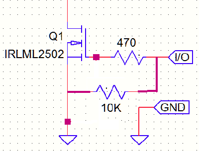
I will just repeat my standard rant re all these drawings that the gate-source resistor should be connected to the driving GPIO, not the gate itself, so a voltage divider won't be created. Even if it works fine as a divider, it's still wrong.