Neat little BLDCs with built-in controller.

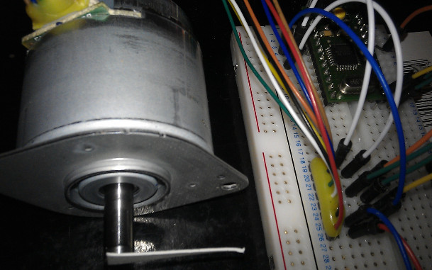
I found some rather handy little 24V BLDC motors on eBay

http://www.ebay.co.uk/itm/DC-24V-20W-High-grade-brushless-motor-brushless-motor-with-encoder-PWM-speed-/261713199819

They do all the work for you, and provide a 400cpr incremental encoder too.

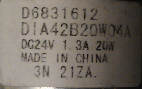
The no-load speed at 24V is 6400rpm, so at 20W they must be about 30mNm
or torque.

So I ordered on and when it arrived I sat down and implemented a Servo-loop to drive
it.

The interface is:
PWM signal (0% = full drive, 100% = no drive, note),
brake signal (active low),
direction signal.

And the quadrature encoder takes a 5V supply and gives AB outputs (no
pullups needed).

Here's my sketch:

// Arduino Sketch turning eBay BLDC motor with integral controller
// into a position-driven servo-motor
//
// eBay motor:
// http://www.ebay.co.uk/itm/DC-24V-20W-High-grade-brushless-motor-brushless-motor-with-encoder-PWM-speed-/261713199819
//
// Mark Tillotson
// 2015-03-13
// 
// tested on 328p processor, encoder code needs porting to Mega...
//
// Creative Commons Attribution ShareAlike 2.5:
// http://creativecommons.org/licenses/by-sa/2.5/
//

//////////////////// pin definitions ///////////////////

// encoder pins and interrupt numbers:
#define ENC_A  2
#define ENC_B  3
#define ENC_INTA 0
#define ENC_INTB 1

// motor drive pins
#if defined(__AVR_ATmega1280__) || defined(__AVR_ATmega2560__)
#  define PWM_PIN 10   // timer2 controls pin 10 on Mega
#  define DIR_PIN 11
#  define BRK_PIN 12
#else 
#  define PWM_PIN 11   // timer2 controls pin 11 on Uno etc
#  define DIR_PIN 10
#  define BRK_PIN 12
#endif


//////////////////// encoder ///////////////////
// [ This code assumes Uno, needs conditionalizing for Mega still ]

volatile long phase = 0 ;
volatile byte portd = (PIND & 0x0C) >> 2 ;

long read_phase ()
{
  noInterrupts () ;
  long result = phase ;
  interrupts () ;
  return result ;
}

// encoder runs at 400 counts per rev, 6000rpm+, so over 40kHz interrupt rate
// thus using direct port manipulation for quadrature decoding.
void handle_enc ()
{
  byte pd = (PIND & 0x0C) >> 2 ;
  pd ^= (pd >> 1) ;     // convert quadrature/Gray to 2 bit binary
  byte sig = (pd - portd) & 3 ;  // calc difference from last sample
  if (sig == 1)
    phase -- ;
  else if (sig == 3)
    phase ++ ;
  portd = pd ;
}

void enc_setup ()
{
  pinMode (ENC_A, INPUT_PULLUP) ;
  pinMode (ENC_B, INPUT_PULLUP) ;
  attachInterrupt (ENC_INTA, handle_enc, CHANGE) ;  // handle every change
  attachInterrupt (ENC_INTB, handle_enc, CHANGE) ;
}


//////////////////// setup ///////////////////


void setup ()
{
  TCCR2B = 0;
  TCCR2B = (TCCR2B & 0xF8) | _BV(CS20); //use a 1:1 prescaler, PWM at 32kHz 

  analogWrite (PWM_PIN, 255) ;  // low PWM means high drive on this motor
  pinMode (BRK_PIN, OUTPUT) ; digitalWrite (BRK_PIN, HIGH) ; // Brake active LOW
  pinMode (DIR_PIN, OUTPUT) ; digitalWrite (DIR_PIN, LOW) ;

  enc_setup () ;
}

void set_drive (int level)
{
  digitalWrite (BRK_PIN, level != 0) ;
  digitalWrite (DIR_PIN, level < 0) ;
  analogWrite (PWM_PIN, 246 - abs (level)) ;
}


//////////////////// PID loop ///////////////////

long target = 0L ;
long integ = 0L ;
long prev_ph = 0L ;

#define P 0.5      // values derived by experiment
#define I 0.001
#define D 2.5

int pid ()
{
  long ph = read_phase () ;
  long error = target - ph ;
  float res = P * error + D * (prev_ph - ph) + I * integ ;
  prev_ph = ph ;
  if (abs(error) < 10)
    integ += error ;
  delayMicroseconds (500) ;
  return (int) res ;
}

//////////////////// test code ///////////////////

int t = 0 ;

void loop ()
{
  // changes target position every 1/128th time round the loop
  t += 1 ;
  if ((t & 0x7F) == 0)
  { 
    int amt = (t & 0x1000) == 0 ? 1596 : 4 ;
    target += amt ;
  }
  set_drive (constrain (pid (), -240, 240)) ;  // run PID and set drive
}

Some photos:

And video: Servomotor test - YouTube
(and in slow-motion: Servomotor test - YouTube - it moves so fast its hard to tell its going 3/4 turn :slight_smile:

Oh, I should add that I hope we start to see more nice BLDCs with built in
controllers like this in the future - this one runs really smooth and quiet
and the encoder alone is worth the price I reckon. So much nicer than
DC motor, no motor driver needed.

My only quibble with it is the flimsy leads - one broke off from vibration in
testing and had to repair it.

I have one of these motors but I can't seem to get it to work right. When I add power to the encoder the motor stops. Could you show a diagram or pic of how you wired it up, I can't tell from the photos or videos you posted. I have

Red +24V
Black Ground
Yellow +5V
White 15-25KHz pulse 80% from function generator
Green +5V

With just that the motor runs and controls OK via PWM

However as soon as I add +5V to Blue it comes to a stop

I have an arduino uno and I'll try that next if you can supply the wiring map that is working for you.

Thanks.

That agrees with the pinout for mine:

red - +24V
black - GND
yellow - brake (active low)
white - PWM (active low)
green - direction
blue - +5V for encoder
brown - encoder B output
orange - encoder A output

The encoder is separate circuitry sharing only the GND pin so you don't
need to supply 5V to run the motor - powering up the encoder shouldn't
have any effect on the motor.

Have you tried just powering the encoder (black/blue/brown/orange) and
seen if its working?

When you powered the blue wire did you remove 5V from the yellow (thats
brake signal)?

The encoder does work when I power it separately and turn the shaft by hand. I wired as you suggested leaving yellow disconnected and blue +5V . Thanks for that. That seems to work. How is the brake supposed to be actuated in practical use?

Hello,
I have been trying to control the motor position for like one month. Basically, I have a motor with quad encoders that give 200 cpr. I just want to implement a PID controller and give specific angles as set points that are then converted to equivalent pulses. Like for 200 cpr, 90 Degree input means 50 pulses thus the motor shaft must move 90 degrees. Unfortunately it does not.

I have written many different codes (after reading a lot of stuff and codes from here and there).

Can you guys please look into it.

P.S: I can't find an attach option here, so I am copy pasting the code below. Don't get mad :slight_smile:

///////////////////////////////////////////////////////////////////////////////////////////////////////

volatile int counter=0;
volatile int val=0;
float Kp=1;
float Kd=0;
float Ki=0;
int error=0;
int lasterror=0;
int sumerror=0;
int pwm;
volatile int sp=78; //set point
volatile int correction=1;
unsigned long time=0;
unsigned long oldtime=0;
unsigned long newtime=0;

void setup()
{
pinMode (4,INPUT);
pinMode(8,OUTPUT);
pinMode(9,OUTPUT);
pinMode(11,OUTPUT);
pinMode (2,INPUT);
attachInterrupt (0,count,RISING);
Serial.begin (9600);
}

void loop()
{

while(correction >0)
{
digitalWrite (9,HIGH); // Anti-Clockwise direction
digitalWrite (8,LOW);
analogWrite (11,correction);
Serial.println(counter);
}

Serial.println (counter);
digitalWrite (8,LOW);
digitalWrite (9, LOW);
Serial.println (counter);
Serial.println ("STOP and wait");
counter = 0;
delay (1000);
correction = 1;

}

void count()
{

counter++;

error = sp - counter;
correction = Kperror + Kd(lasterror - error) + Ki*sumerror;
if (correction >255)
correction = 255;
if (correction <0)
correction = 0;
lasterror = error;
sumerror = sumerror + error;

}

Firstly the error input and control output from the PID loop must be signed values,
you need to control in both directions!

Separate out the code that reads the position, and writes the motor driver PWM, each
interfaces to the PID loop with a signed value.

Lose the integral term for now, integral-wind-up will bite you, just
get P working, then PD.

When you add an integral term you have to do something to quench integral wind-up
or your system will misbehave - typically you'd only do the summing when the error
is small (ie you are close to the true target), otherwise the errors summed when the
system is out of equilibrium will dominate.