I'm trying to control the position of a 24V bldc motor with on-board encoder. I cannot really figure out what kind of encoder though..
It seems to have only one channel instead of the usual two (for so far I can find).
I am using an arduino mini pro.
Now the blue wire is on A0, and the green wire is via a button connected to ground. When the button is pushed, the motor runs.
The code now is to check what happens. I am just not quite sure what I am seeing, and how to continue.
What I want, is to be able to control the motor position.
Any help ?
Why posting a screen shot of your code instead of the actual code? You don't want us to read and check it out or so? Posting an image of your scope output would be more useful.
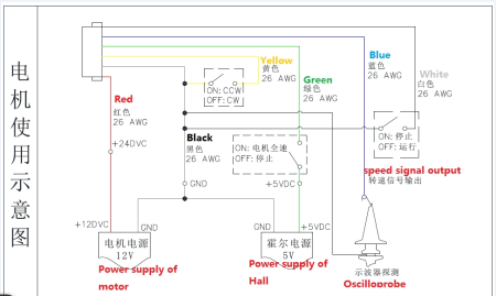
OP's only useful image, the circuit diagram:
How does your circuit step down the 24V to 12V? It's drawn as if it's directly connected. Something is wrong there.
Oh, and do read this. It's on top and in bold not just because.
Good tip, wvmarle, not meaning to keep it from you guys..
int input_HallSensor = 0 ;   //blauwe draad

int LED3, LED4, teller, HallSensor, countPulses;

  void setup() {
    Serial.begin (9600);

  attachInterrupt (0,countPulses, RISING);
  }

    void countPulses(){
      pulseCount ++;
      volatile undigned long pulseCount();
    }
      while (teller < 139 ){

      HallSensor = analogRead (input_HallSensor);
        if (HallSensor == 0){
        Serial.print ("LED3 loop is: ");
        Serial.print (HallSensor);
        Serial.println();
        }
        if (HallSensor != 0){
        Serial.print ("LED4 loop is: ");
        Serial.print (HallSensor);
        Serial.println();
        }
      }
The diagram is a bit of a mix of the motors the manufacturer makes. Power supply is 24V.
I've been searching for a while, but I keep coming back to encoders with 2 channels instead of one (the blue Hall sensor wire).
Please do make sure your code at least compiles before posting it!
while (teller < 139 ){
Not only is this outside of a function (so won't complile), as teller never gets assigned a value this either never runs or becomes an infinite loop (in regular C++ that is - in the Arduino IDE it will be automatically assigned 0 upon declaration, so it's an infinite loop).
volatile undigned long pulseCount();
Also won't compile. The function itself is missing, too.
 if (HallSensor == 0){
        Serial.print ("LED3 loop is: ");
        Serial.print (HallSensor);
        Serial.println();
        }
Not very useful, is it?
Another thing: use the F() macro to get all your fixed strings stored in flash, and use the smallest possible data type (an int is two bytes, a byte is 1 byte in memory - do you really need them to be an int?), and make values that can never go negative unsigned.
Thank you for your feedback, wvmarle..Sorry, kind of searching here.. I will try again:
I am currently using a 24V BLDC motor, with gearbox – ratio 1:139. The motor is controlled by a microcontroller which is included on the motor. The motor is turning without any code, simply by connecting it to 24V.
I want to find a way to control the controller so that the outgoing axle:
-
Starts from one specific angle (say 0º)
-
Make one complete rotation (either cw or ccw)
-
Make one part of a rotation (say ¼, cw) and come back to the start angle (moving ccw).


I did connect the blue wire from the motor to an oscilloscope, which gave values differing from 0-5V with a 50% duty cycle. Speed of the motor is dependent on the voltage; 24V is full speed, anything less means less speed.
Previous codes shown were more of a way to try to determine what kind of signal was coming from the blue wire, should I use digital or analog input, and how further..?
Does anybody have any experience with the readout / control of this kind of setup?