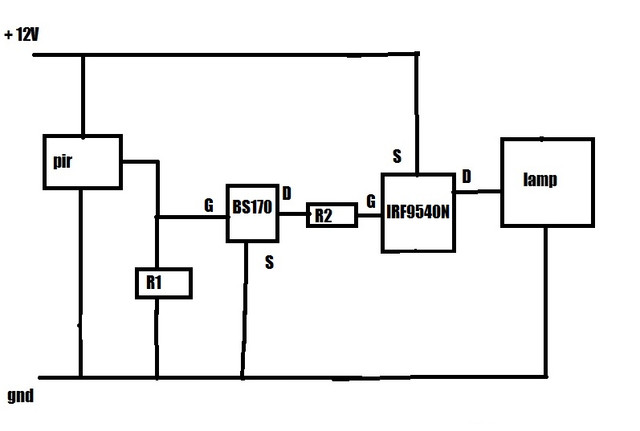
Year ago I had a schematic and bought parts over ebay, without thinking much about physics and it worked out just fine. MOSFETs used were BS170 and IRF9540N and pir sensor is HC-SR501.
I would like to know:
What values of these two resistors would be standard for 12V ?
What is the meaning of ground symbol, does it mean that it needs to be physicaly grounded ?
Which MOSFET and resistor would you recommend for the following to power on led:
signal is +3.3V gate opens
signal is +5V gate opens
signal is +12V gate opens
signal is Low gate opens
with voltage on led no more than 12V and max 15-20 W
and voltage on led no more than 5V and max 15-20 W
Can voltage that travels through gate be lesser than treshold voltage ?
IRF9540N is a P-channel MOSFET (odd choice of part numbers there). Accordingly, it is connected in the standard manner (the opposite of how an N-channel MOSFET is wired): Source to the positive supply rail, drain to the positive side of the load. To turn the fet ON, a voltage on the gate needs to be applied which is lower than the voltage on the source (again - opposite of N-channel fets).
It looks like you're working with a PIR sensor with an output that goes HIGH in the event of motion (odd - most of the PIR units I've seen have active low outputs, often open drain ones), and possibly at a lower voltage as well. The second N-channel fet is used to invert the signal (so the applied voltage from the PIR output turns that fet on, which pulls down the gate of the fet and turns it on), as well as handling the 12v on the gate when the PIR device may output a lower voltage.
R2 is unnecessary as far as I can tell - a resistor like that is advisable when driving the gate from a microcontroller pin, because (acting as a capacitor) there'll be a brief pulse of current during switching that could damage a microcontroller pin (this might be more of an issue with large fets with higher gate capacitance - I have never had issues driving the gate of small mosfets directly off a microcontroller pin). But with a MOSFET driving that pin, I can't imagine you'd need that resistor.
There is a missing resistor between the gate of the IRF9540N and the source (ie, +12v power rail) - without it, the gate will float, and could turn on or off in response to ambient electric fields.
I suspect you may have miscopied the design when making that drawing, and R2 is actually that "missing" resistor, and is connected between the '9540N gate and +12v, not between the 9540N gate and the smaller transistor's drain as you have shown.
tehawk:
Year ago I had a schematic and bought parts over ebay, without thinking much about physics and it worked out just fine. I dont have schematics anymore but I made a drawing about circuit, it can be possible that I did not draw it ok.
There are parts I do not understand:
What is the purpouse of R1 resistor ?
To switch off the N-channel FET when the PIR is driving its gate high. It might not
be needed if the PIR can also pull low.
Why is there R2 resistor ?
No reason, its a mistake. Or more likely it should be between the p-channel FETs gate and source to
switch if off when the n-channel FET is off.
What is going on between BS170 and IRF9540n ?
The n-channel BS170 is level shifting the PIR's logic output to 12V switch, so it can drive
the p-channel IRF9540's gate by 12V, which it requires. Its not clear what the PIR device is and
whether it outputs only a 5V logic signal or higher voltage. The combination of n-channel (logic level)
device driving a p-channel device allows a 5V signal to control the load switched at the high-side.
Alas the BS170 is not logic level, so its not ideal for this use (though it depends on the PIR unit's
output voltage).
What are the values of R1 and R2 resistors ?
Depends on the requirements - particularly of switching speed, power drain and noise immunity
tehawk:
Thank you very much for answers and schematic.
I do not understand how p mosfet works, n when have high on the gate opens but then p should have also high and be closed.
Absolutely - you do understand, but remember the n-FET pulls the output low, which turns the p-FET on (pulling
its output high). Each stage inverts the signal/voltage.