Hey guys,
For my work, I need to read values from sensors every 4 hours. To save energy, I use the deep sleep mode and the transistor 2N3906 (PNP) that I switch ON/OFF just to get data from my sensor. The battery is a 18650 and I use a 1000uF with the MCP1700 regulator to get 3.3V. So both the ESP and the potentiometer are using 3.3V. I made this and it's working fine:
Sorry, I know, there are better ways to show this...
Now, I have to use another sensor which uses 12V input. I'm not good at this and too scared to burn something. I would need help to design a schematic to power both the sensor and the ESP. I will use a 12V battery of course. I just don't know how to position the transistor... and the rest.
Transistors are "current multiplying" devices; that essentially means for a rule-of-thumb calculation, the collector current divided by the hFE gain will be the base current required.
The common-emitter DC gain (base-to-collector current gain, hFE) is calculated by hFE = IC/IB with VCE at a constant voltage . hFE is also called βF, the forward DC current gain. It is often simply written as β, and is usually in the range of 10 to 500 (most often near 100). hFE is affected by temperature and current.
For the ESP power you'll need a (switching?) voltage regulator which you cannot turn off because that's the job of the ESP.
Depending on the sensor type it may be better to add a step-up converter from your 3.7V battery to the sensor supply voltage. Then you can turn off both sensors by the single transistor. Eventually a stronger transistor or MOSFET is required for the common switch.
Not sure what you are trying to do, the picture is a little help. Schematics are much better, that would show the bypass capacitors and bulk capacitors. You will normally only have ground on the potentiometer, no clue what the 2N3906 does or how it is connected although I could assume it is a high side switch. It appears you want to use the pot to simulate the DC output of a sensor. Connect one side of the pot to 3.3V the other side to Ground and connect the wiper to A0. Once you get that working use a resistor divider, here is a calculator link. Voltage Divider Calculator Be sure the grounds are connected. Links showing technical information on all of the hardware devices including the micro. Using a MOSFET as a switch is much simpler and uses a lot less current.
@mrburnette@DrDiettrich@gilshultz Thanks to all of you. I think the road will be long before I can digest all these new concepts but I will make it!
To be clear @gilshultz, what I'm showing is an example of how I was doing with my potentiometer (it is using 3.3V). This time, I will use a piezometer which needs 12V. And I was hoping to get a working schematic I could use to power my ESP with 3.3V and be able to switch the piezometer off from the ESP. I just don't know how to arrange things.
I've looked for MOSFET some time ago but I'm lost. I don't know how to choose them. There are so many. Which one would you recommend in this particular case? And do you think you could help me designing the schematics? Sorry, I'm probably asking too much. I need to learn by myself.
I will definitely read the resources you gave me.
Thanks again
Laurent
The IRF520 is a Power Mosfet with a 9.2-ampere collector current and 100-volt breakdown voltage. This MOSFET has a low gate threshold voltage of 4 volts and hence is commonly used with microcontrollers like the Arduino for switching high current loads.
So, if using 5V Arduinos and switching high currents, the above would work. But, if using 3.3V Arduinos, you need to look for:
datasheet there is an on-resistance quoted for Vgs <= 3.0V
Keep in mind that Adafruit and Sparkfun are competitors in the Arduino space, so play them against each other; sometimes the info is the same, sometimes a bit different, always FREE. https://learn.sparkfun.com/tutorials/transistors/all
There are thousands of books and tutorials out there that will help you. A good start would be the Arduino Cookbook, It has everything you want but in small bytes instead of one program/schematic. This will take some time to get comfortable with it but you will be very happy in the long run if you do. You will want to eventually get some sort of schematic capture program, I use KiCad, I can go from concept to a complete set of Gerber files to make a PCB. Using any portion of it will help you gain understanding. Be warned it is not a simple program but the schematic capture is not to hard. Let us know how you are doing. Any attempt at a schematic is always welcome and much better than a frizzy picture. You can start with a pencil and paper and post that so you can ask questions that are easier for us to understand. We do not expect it to be perfect. Even simple labeling helps such as placing E, B, C on your transistor. You have already come a long way, look forward to a long and fun filled journey.
Excellent suggestion. I think I need to go through the basis. For sure, if you can show me some schematics related to my problem, it might help.
I will have some time during the holidays so I can read on it and come back stronger!
Thanks
Thanks again @gilshultz, @mrburnette and @DrDiettrich for your suggestions. I read this Arduino cookbook, a couple of articles and watched a few videos and I'm a bit more confident now.
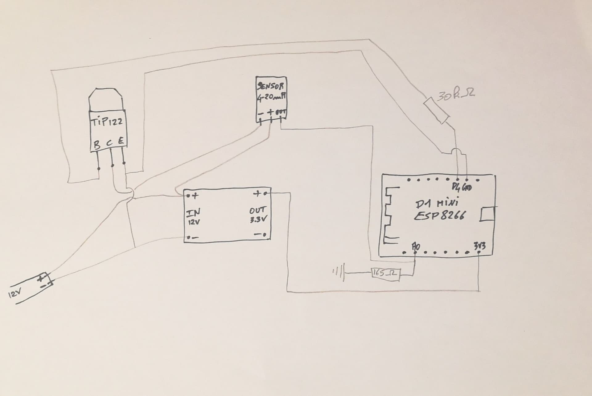
I came up with a schematic, I tried it and it's working fine. The only MOSFET I received at the moment is the TIP122. I will receive the IRF520 and others later.
My question is this one. My sketch goes to deep sleep between each measurement but the current is still 15mA during this period. There must have a way to optimize it. Could you please tell me how?
As a reminder, I'm using the mini D1 esp8266 (I'm planning to switch to esp32 soon, maybe I should use it here?!). My sensor is a piezometer (4-20mA) which requires a pull down resistor of 165 ohm. This part is correct as I tested it before. The problem should be more around the MOSFET. I calculated the value of the base resistor as shown here:
Find the impact of the sensor by manually connecting and cutting the Gnd connection. You can do this with only the sensor and resistor. I'd think that turning off the Gnd is not the right way to preserve power, you better turn off Vcc (+).
BTW TIP122 is a Darlington BJT with considerable voltage drop. A MOSFET will switch better but this may not be significant right now.
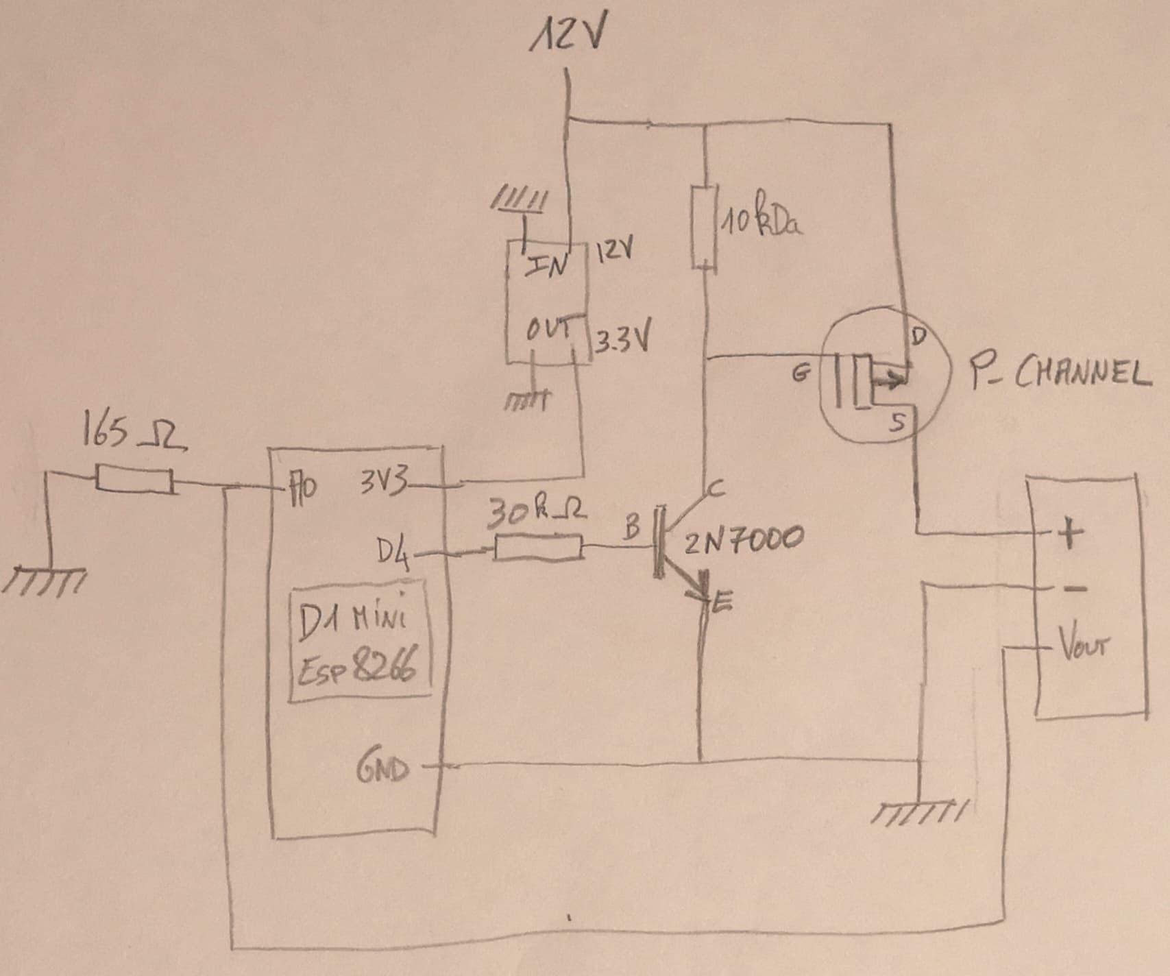
My complements, you have come a long way in your understanding. I am impressed with your schematic, especially for the first time. You can use a p-channel MOSFET as a switch for the sensor. Since you are switching 12V from a 3.3V system you need to do a level conversion. Connect the source to +12, Drain to your sensor +12V. To turn the mosfet off connect a 2K - 10K resistor from the gate to the source. The P-Channel needs a negative voltage on the gate to turn on. This is as it is with MOSFETs referenced to the source, not ground. You can use a logic level such as a 2N7000 (not much current need). Check the data sheet for the 2N7000 not all will work with 3.3V. Connect the source to ground, the drain to the gate of the P-MOSFET and the gate to a port pin that has a 10K pull down resistor. You can make a schematic of this, when you do it should make sense. You will be using two very common circuits together.
Thank you very much for your words @gilshultz.
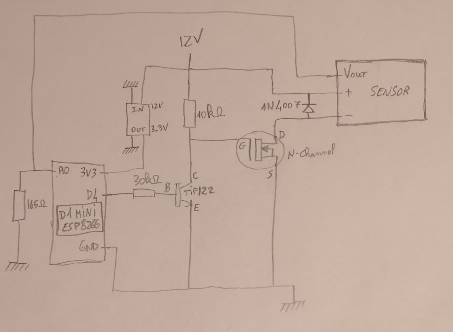
So I read more and following your advices, I came up with this schematic. I don't have any P-channel so I decided to go with the N-channel. I have in stock: IRLZ44N, FQP30N06L, IRLB8721, 2N7000. Plus, I read this:
Still, I will order a P-channel MOSFET. Would the IRF9540N be appropriated for this?
Before I burn something, can you please check if I did something wrong.
You can call the fireman but it will be a very small one. You can do this but the sensor will probably feedback 12V to your A0 input blowing the port. Stay with the high side switching, switching the ground (-) can lead to backfeed problems.
A simple rule P (P-Channel) is for Positive and N (N-Channel) is for Negative.
Try the 2N7000 in place of the TIP122 it will probably work but you need a P-channel MOSFET on the +12V. Since there is nothing inductive in your sensor the diode is not needed.
It looks great. The turn off of the MOSFET will be slow because of the gate capacitance. You might want to make it in the 5-10K range. It will still be a little slow but ok. Your schematics are getting better, keep at it.
Thank you so much. I realize now how important it is to make schematics. It really helps to understand how things work.
I will also have to add a SD card module later.
I will test it as soon as I receive the IRF9540N and let you know.