Hello,
I'am making a project using esp32, it has a lot of components but the thing is that i fried my esp32, everything worked fine on breadboard and when I soldered one day everything worked and the other day esp32 got fried and I don't know why.
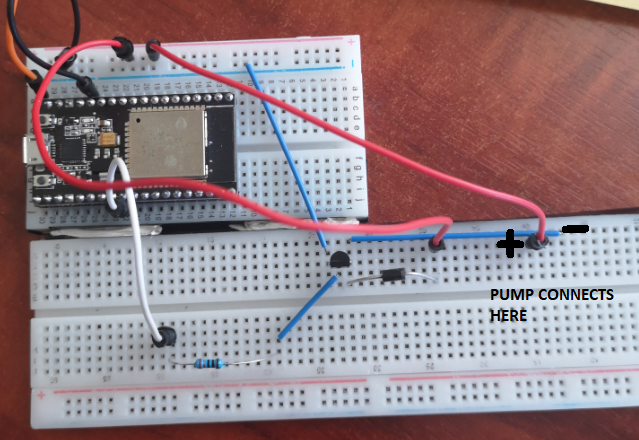
So there is one part of the circuit that controls 5V DC water pump with transistor. Base connected to esp32 with 220 ohm resistor, collector connected to diode and 5V, emitter connected to ground.
So I measure voltage with multimeter between esp ground pin and base pin, and it gives around 0.5V to 1V, also gives 1V to water pump pins, which should only get 5V when esp pin is High. And I don't know is it normal to get some voltage out of transistor without pulling base high or my transistor is dead. Transistor I'am using is 2N5551, diode 1N4148. My guess is that somehow transistor died and fried my esp32 but I'am not sure, any ideas?
I just ordered another esp32 but afraid to test it in circuit, don't want to fry it.
This is my pump control circuit, I'am not good with transistors, I think that my circuit is bullshit. I used one tutorial to connect it, there was a different transistor but i connected it so it would be the same, and it actually worked on dreadboard, but i guess not properly.
I don't see anything on there that supplies power to the pump, although that could just be because it's hurting my eyes trying to follow the wires.
Please post a schematic, hand drawn and photographed is fine. We don't mind if it's a mess (but surely you own a ruler and know how to use it), we do mind if it's not accurate.
Thank you, much better.
It does not show on your schematic which is collector and emitter. Emitter should go to ground and collector to the pump-ve.
How much current does your pump require? The important figure is the stall current of the motor, which you can find my measuring the resistance of the motor and using Ohm's Law to calculate the current, so 5V / whatever resistance you calculate. Most likely this will be a lot more than the run current.
If you look at the 2N5551 datasheet the maximum collector current is 600mA. I would think that whatever transistor you use needs to have a rated collector current at least twice what you calculated above.
With a 220Ohm resistor on the base you have 3V3 (ESP32 OP voltage) - 0.7V (BE voltage) = 2.6V across 220Ohms = about 11mA to drive the base. As the transistor needs to be saturated this is good for about 100mA collector current, so that's the limit for the pump. Again, what is the stall current of the pump motor?
A 1N4148 has a maximum forward current of 150mA. The diode needs to be rated for at least the motor stall current.
So, unless your pump motor is tiny and only needs about 100mA maximum, expect smoke.
PerryBebbington:
It does not show on your schematic which is collector and emitter. Emitter should go to ground and collector to the pump-ve.
So I added a photo from datasheet, in my case its from left to right EBC(Emitter Base Collector), so I guess I connected correctly?
How much current does your pump require? The important figure is the stall current of the motor, which you can find my measuring the resistance of the motor and using Ohm's Law to calculate the current, so 5V / whatever resistance you calculate. Most likely this will be a lot more than the run current.
So I measured the resistance and its 12,5 ohms, so 5/12,5= 400mA, I should change the transistor to support atleast 800mA? also diode is too weak then.
With a 220Ohm resistor on the base you have 3V3 (ESP32 OP voltage) - 0.7V (BE voltage) = 2.6V across 220Ohms = about 11mA to drive the base. As the transistor needs to be saturated this is good for about 100mA collector current, so that's the limit for the pump. Again, what is the stall current of the pump motor?
Didn't really get this part. So I should change the resistor to less resistance?
So I added a photo from datasheet, in my case its from left to right EBC(Emitter Base Collector), so I guess I connected correctly?
As far as I can tell, yes, that's correct.
So I measured the resistance and its 12,5 ohms, so 5/12,5= 400mA, I should change the transistor to support at least 800mA? also diode is too weak then.
There's no absolute rule, I would prefer a margin of 100%, but if it really only needs 400mA and you have the transistor then probably OK. Yes, your diode is not suitable. I would use something like a 1N400x (last digit doesn't matter, they are all 1A and rated for different maximum reverse voltages).
Didn't really get this part.
The transistor needs to be saturated (use your favourite search engine and research saturated transistor) to work properly as a switch. Rule of thumb base current needs to be 1/10 collector current, so at least 40mA. Check the maximum output current for an ESP32, I think it is a lot less than 40mA, but I don't know for sure. This means you cannot use a single BJT to do what you are trying to do. Ideally use a logic level FET.
The transistor needs to be saturated (use your favourite search engine and research saturated transistor) to work properly as a switch. Rule of thumb base current needs to be 1/10 collector current, so at least 40mA. Check the maximum output current for an ESP32, I think it is a lot less than 40mA, but I don't know for sure. This means you cannot use a single BJT to do what you are trying to do. Ideally use a logic level FET.
But it worked on dreadboard perfectly, I understand that the mqgic smoke escaped because I used a bad transistor and diode, but if this was the problem, then it would not work at all, but it worked for a while. I mean I tried a lot of times and transistor was saturated
Maybe you were on the limit and it survived for a while, impossible for me to say. All I can say is based on what you've told me the transistor and diode are probably being pushed beyond their limits.
PerryBebbington:
Maybe you were on the limit and it survived for a while, impossible for me to say. All I can say is based on what you've told me the transistor and diode are probably being pushed beyond their limits.
I agree that it was pushed to the limits and it fried, I should change transistor and diode with higher specs, and it should work, because it was enough current to saturate the transistor before and it will be enought with higher specs??
I don't believe it will saturate the transistor, for 400mA you need ~40mA base current. Less than that it might be OK but don't count on it. In any case, this is the 21st century, you really should be using a MOSFET.
MarkT:
Post the datasheet or product page link for the pump, then we can figure out what is needed to switch it.
found this link, I bought it in different store, but its the same as I use. I can't find a normal datasheet, but I thought this pump is really low current and won't be a problem controling it...
Also I tried to test the circuit, switched the supply on and tested the pins that comes from transistor to pump, it gives 1.5V, in my undestanding when transistor is not saturated in those pins should be no voltage, but tried to pull HIGH the base pin and it gives 5V as it suppose to.
Also I tried to test the circuit, switched the supply on and tested the pins that comes from transistor to pump, it gives 1.5V, in my understanding when transistor is not saturated in those pins should be no voltage, but tried to pull HIGH the base pin and it gives 5V as it suppose to.
I've read that several times and I still don't know what you mean, sorry.