I want to create a button box for a trucking simulation game. I have figured what buttons I want and the layout for them. I just do not know how to do the wiring. Does anyone know how to wire them to an ARDUINO UNO REV3 MICROCONTROLLER ATMEGA328P (diagram below)? And would I need to use resistors or anything else similar? If you also happen to have the code needed that would help a lot to. Your help is greatly appreciated!

Each normal switch is wired to a pin on the Arduino and to ground. in the setup() section you'll have a
pinMode(pin#, INPUT_PULLUP);
one line per switch. This tells Arduino to supply the needed pullup. The swiches are active low, so you'ld code something like this in the loop() section
if (!digitalRead(pin#)) {...} // Button pressed
Your keylock switch should control power (or gnd) to the entire panel.
Okay sorry this is my first time using these forums. This is my first time trying a project like this and I know very little. After a little research, I came up with this diagram for the wiring below. I just don't know how to wire in the lighted push button, the on/off rocker switches, and the momentary rocker switches (that is also if everything else is correct, I could be totally wrong). I also realize that the rotary encoder has 3 other wires connected to it - one to the ground, one to TX and one to RX, there just wasn't enough room to put them and have the diagram still make since. I believe there is an Arduino joystick library out there that has code that you would use for a project like this, but I know it's going to have to be modified and I have no experience or knowledge of coding. I left out the diodes because I couldn't figure how they would be wired in series with each button and so that can be figured out afterwards. Thanks again!


Okay I understand the diodes know. Connect one end to the switch and one to the column or row. Just need to figure out the rest now.
I just looked up Schottky diodes and found some places that say it's better to use a fast recovery diode. Is one better than the other for this type of project? Or is it just flip a coin which one you choose to use?
This page may have information of interest. What is the difference between Schottky and Fast Recovery Diode? | Forum for Electronics
Okay it sounds like Schottkys are better in this instance. I think I will use those. Now I just need help with the wiring of a few buttons and coding (found in post above). Thanks for your help so far!
I think that you can use the keypad library for the programming.
Do you want your button box to act like a HID (mouse/keyboard)? If so, I would suggest to use a board that supports that; e.g. Arduino Leonardo or Micro.
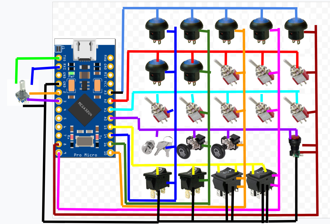
Yes I want to use it like a keyboard. With this new information, I put together a revised diagram using a Micro, but I still do not know how to wire the on/off rockers, momentary on-off-on rockers, and the lighted push button. (The rotary encoder also has wires going to GND, TX, and RX, it just made the diagram to messy to put them.)

The on-off rocker switches can be wired common to ground and NO to an input of the matrix.
The on-off-on switches would be treated as 2 switches. Common to ground and each of the other terminals to the separate input of the matrix.
The switch part of the lighted push buttons wired as normal. The LED parts, I suppose, could be wired to individual Arduino outputs or maybe into their own matrix.
I would not try to make the encoders part of the switch matrix. Handle them on their own. The Encoder library makes interfacing the rotary encoders easier.
It looks like there are at least ten maintained contact switches. You may have issues with rollover if enough of them are closed simultaneously. Also if just enough are closed to work properly and then one of the momentary buttons is pressed.
Most switches won't be used at the same time. It's mostly a one button press to activate or turn something on. The diodes should help some with rollover. Unless you mean if I say had all the toggle switches in the up position, that this would cause rollover. Is there a way to prevent this?
Some of the terms you used I am not sure if I understood them correctly. I put a new diagram below of what I did. I wired all the rockers and light switch and the encoder to the same ground. The momentary rockers had their wires duplicated onto the same row/column so that both switches would work. And I left the encoder out of the matrix. The light switch I believe needs a ground and then I connected it into the matrix (2 wires for the switch, 2 for the light), however there is room to have this button separate from the matrix. Again, not sure if I interpreted what you said correct. Please let me know.
That's what I meant. It just depends on how much rollover the code will provide. You'd have to investigate different libraries to find out what's possible.
If you use a shift register each key essentially has its own spot in an input image and all key interpretation is done in the controller so there's no issue with rollover or ghosting. The downside is it requires more hardware - one shift register per eight inputs, with its accompanying decoupling capacitor*, and one pullup resistor per input.
Or, you could use an I/O expander chip like the MCP23017. It's still added hardware but this device will give you sixteen configurable I/O, interrupt capability, and has settable internal pullup resistors. Not surprisingly, there are libraries to run this chip, too, so you don't have to deal with the nitty gritty of setting individual pins. And, since the MCP23017 can do outputs you could drive your LED with it.
*Any external digital chip needs one of these mounted near it.
+1 for the MCP23017. Each MCP23017 has 16 GPIO pins and is I2C interface so up to 8 of them (128 extra pins) only uses the 2 I2C pins.
The MCP23017 has internal pullups (just like the mega328 chip) so no external pullups required. Also, the MCP23017 has pin change interrupt (per 8 bit port) which may be handy. Driving LEDs would need external resistors, of course.
A MCP23017 library. GitHub - adafruit/Adafruit-MCP23017-Arduino-Library: Arduino Library for Adafruit MCP23017
I want to clarify because this is getting a bit confusing for me. Basically I can use the MCP23017 to add extra I/O pins. With this I would want to give each button/switch its own input/output pins. If this is correct, and this may be asking a lot, how would the wiring work, connecting the buttons/switches to the chip and the chip to the board?
Basically I can use the MCP23017 to add extra I/O pins.
With this I would want to give each button/switch its own input/output pins.
Yes
If this is correct, and this may be asking a lot, how would the wiring work, connecting the buttons/switches to the chip and the chip to the board?
Same as the Arduino I/O

ARDUINO communicates to the chip via SCL and SDA.
So as long the board has a power source connected, and is connected to the chip via SCL and SDA, it should work. Then each button/switch gets 2-4 pins dependent on the button type (GPA0-GPA7 and GPB0-GPB7). Can all the buttons that need a ground be wired to the same ground? (Assuming there is a ground, as I don't see any GND pins in the diagram above). And which pins would act as the TX and RX pins for the rotary encoder?
Can you connect more than one chip to one microcontroller? And if you run out of space on the chip can you wire some of the buttons into the microcontroller?