Hi everyone, I'm very new to this and would like to get this display working. I tried to get it to work but can't figure out how, any help is appreciated

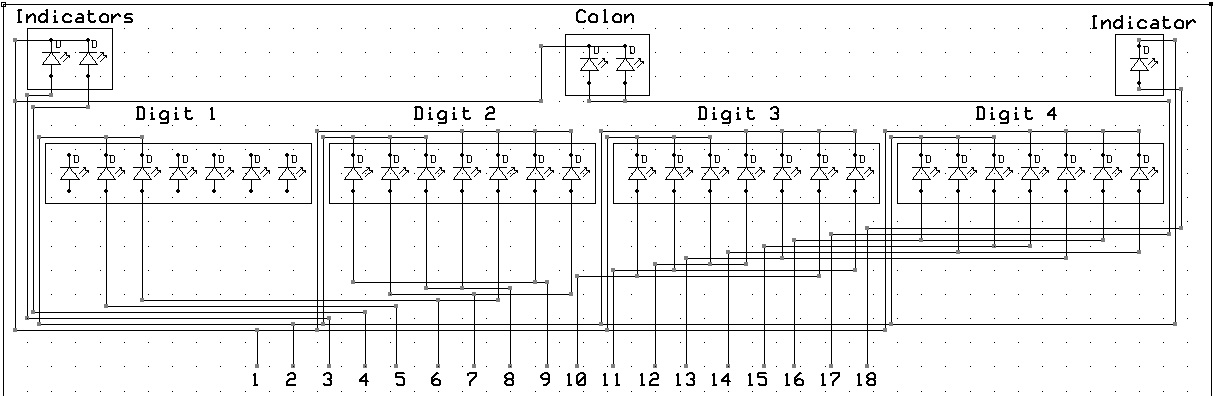
Google finds this but it seems the guy never made it back home to redraw it. It seems a plausible drawing if the display is out of a 12 hour clock where the first digit is either blank or 1.
That link led me to the pinout I needed, and now I'm getting some of the digits lighting up, time for some breadboard testing, thanks! ![]()
hmmm, strange . . . I can't figure this out. There's 16 digits, and 2 ground wires that apparently can create all the numbers from 00 to 59, naturally there's combined LEDs in these digits, but I can figure out how some numbers were generated, 27, 48, and 56 for example. Unless they flicker at different frequencies and require PWM or something. Can anyone she some light?
You need to use 2-way multiplexing. First you ground one of the ground pins, and drive some of the 14 segment pins high through series resistors to get 2 digits displaying what you want. Then you ground the other ground pin and drive some the 14 segment pins/series resistors high to get the other 2 digits. Repeat this quickly enough to give no apparent flicker. I normally use a tick interrupt to switch the multiplexing over at regular intervals, but with care you can do it in loop() instead.
You can drive the segment pins directly from Arduino outputs through series resistor of about 150 ohms, but you will need to use NPN transistors (e.g. BC337) to ground the ground pins because they each carry the current for up to 14 segments at once.
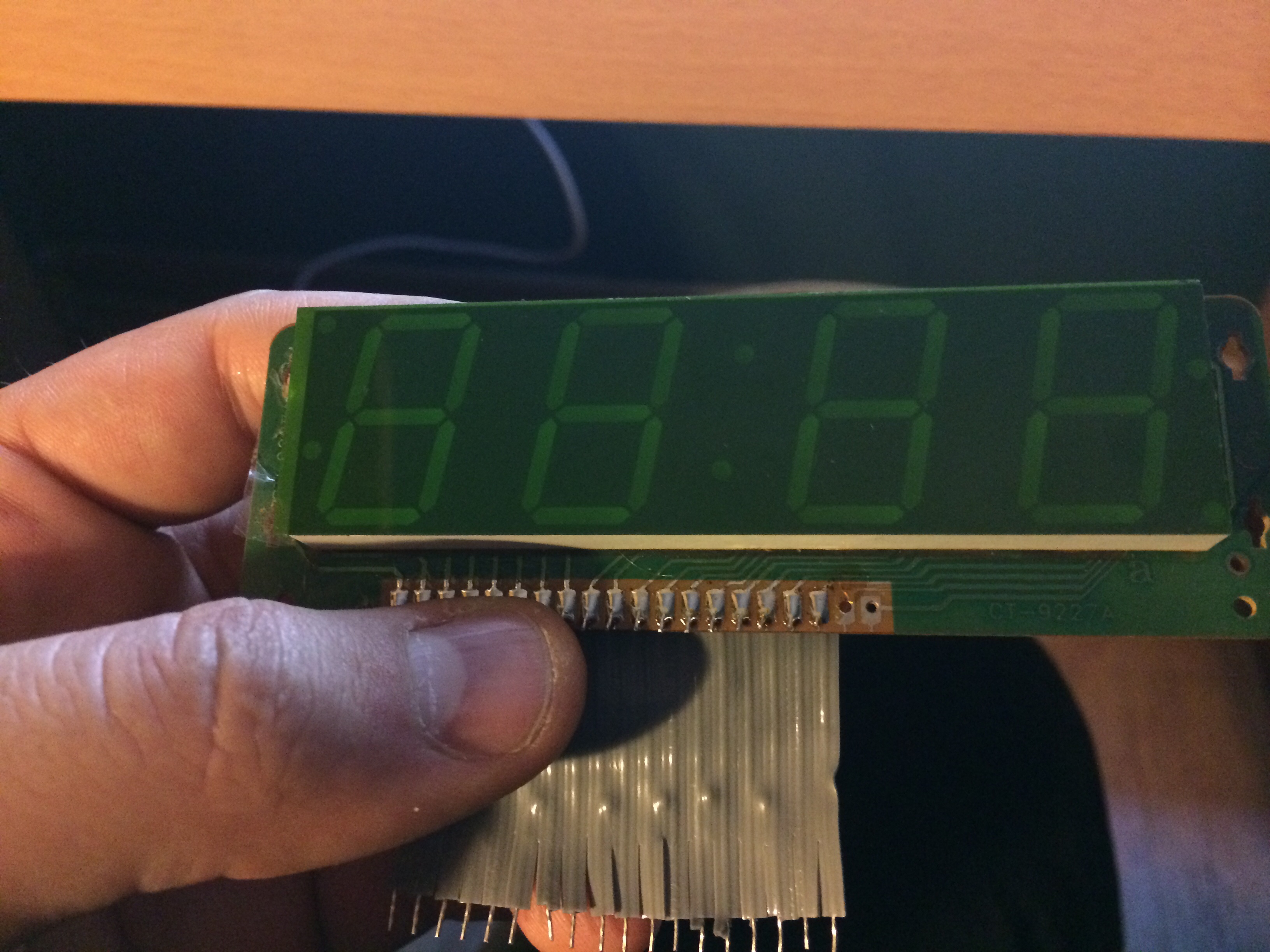
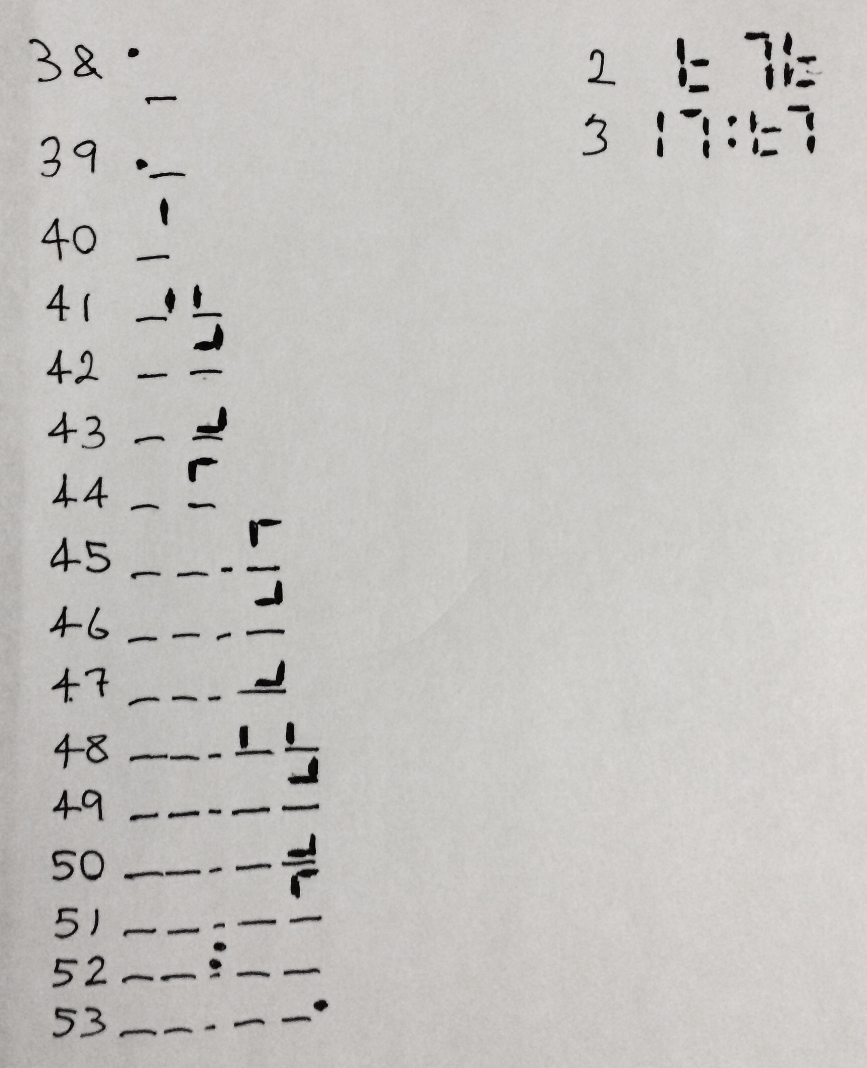
Thanks for the reply, I understand the concept of multiplexing, but even with that I can't seem to generate those values. I've attached what I get when applying 5v to each of the digits while grounding the two cathodes, as well as what digits the cathodes have control of (pins 2 and 3). Can you help me in figuring this out?
Here's a high speed vid of the digits activated 1 by 1
Heh, well, you don't seem to be quite following the idea of multiplexing here.
Usually to multiplex multi-digit displays, you enable one digit at a time and drive whatever segments you wish to light up for that digit, then disable the first digit and enable the next one and so on. All digits use the same segment pattern.
These clock displays (and only 12 hour ones at that) are based on using a centre-tapped winding (about five or six volts per side) on the power transformer so that each end is connected to one cathode rail and the cathodes are alternately pulled negative at the frequency of the power mains. Another tap on the transformer supplies the input to the clock chip that it uses to keep time, but also to switch between alternate sets of segments.
The point is that all the segments of each of the two alternate groups that are intended to be illuminated for the particular image, are driven at once, notwithstanding to which digit they correspond. You need twelve lines to drive the segments (being three digits x seven segments plus the two segments of the MSB and you will need to have a current limiting resistor for each segment connection) and optionally another two for the colon, alarm and AM/PM indicators. Unless you happen to be using the same power transformer arrangement as the clock, you will in fact need a couple of NPN transistors to alternately select the cathode lines - you only need one more MCU pin to do this.
Obviously you will have to code the mapping of the various segments yourself as it is nowhere near the same for each digit.
These displays are very good for making clocks, though - if you can put up with the 12 hour time. ![]()
Ohhh, I understand now! I need to light the digits one at a time and disable the necessary cathode and persistence of vision of the human eye will see them on consistently! Thanks! I mean I don't understand what the MCU, MSB, and centre-tapping means, but I get it now, lol
majinjeff:
Ohhh, I understand now! I need to light the digits one at a time...
Actually, two at a time for this type of display. See Paul's response below.
No, you need to light segments from essentially all digits - as needed - for one half of the time, and the other group of segments the other half of the time.
Got about half the digits mapped out, next step is the fun part; coding applications! Maybe a binary counter or custom alarm clock ![]()

