Hi! I really need help with wiring in the button box project i made. Its my first project ever and i really lack knowledge in wiring. To me it seems alright, but im sure that smthing is so wrong.
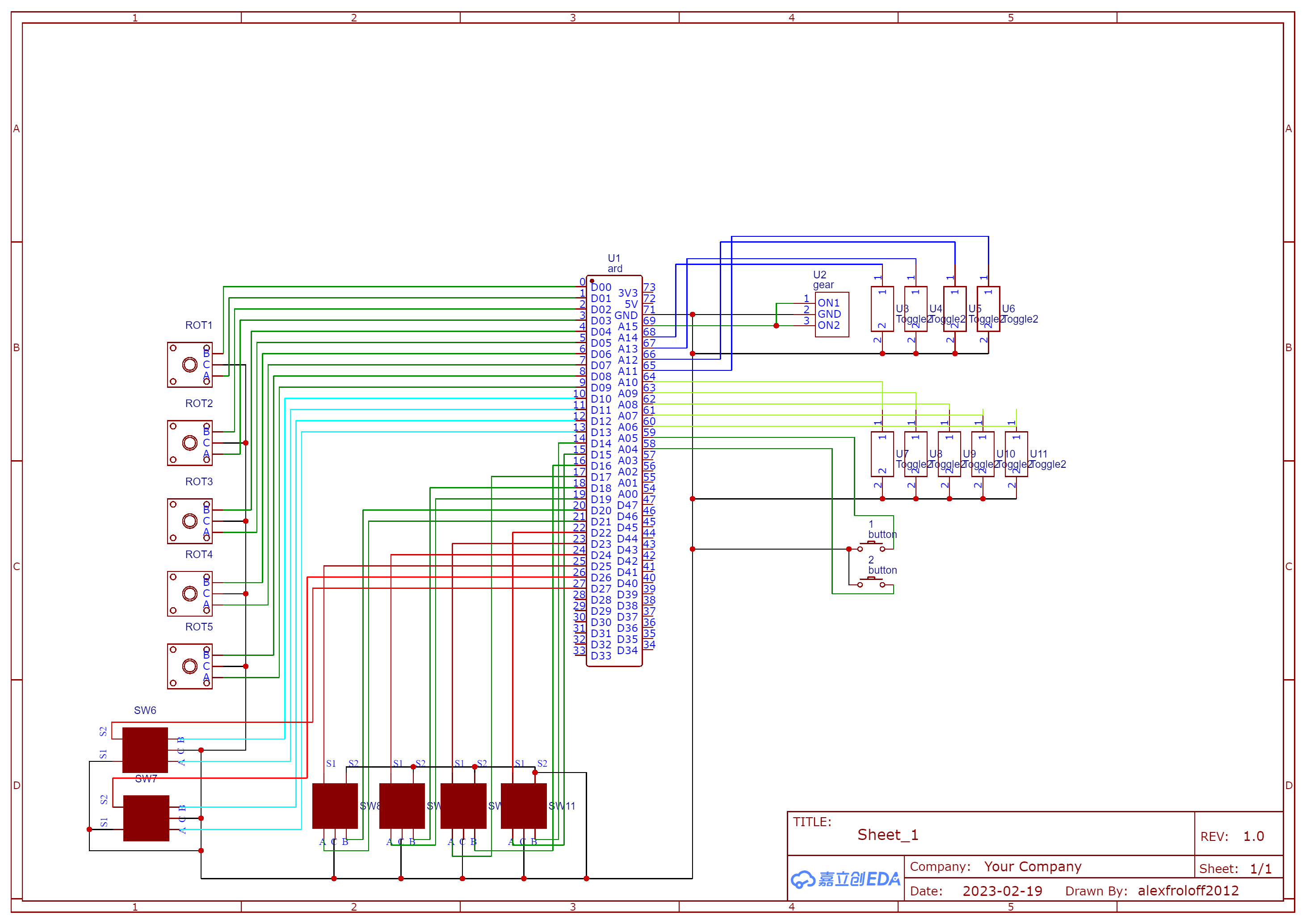
I attached wiring scheme for arduino mega that consists of 6 rot encoders with buttons (sw6-11), 5 rot encoders no buttons (rot1-5), 2 buttons (button1-2), 9 toggle switches off-on (above buttons) and 1 toggle switch on-off-on.
The toggle swiches (off-on) really only need ground and 1 wire to an input set to pinMode INPUT-PULLUP. If the switch is not on it must be off. Edit: the SPST switches already seem to be wired like this.
SPDT (center off) need a wire to ground and one from each to an input set to pinMode INPUT_PULLUP if both positions need to be sensed.
Thank you for advice. SPDT switch wired like this because both on(up/down) will execute the same button. I use this switch just for the additional emmersion
On other forum people wanted me to elaborate on my problem, so heres my main questions:
Is it even wired correctly (will it work)?
I've seen schemes in similar projects using 1kOhm (or smthing like that). I feel that i need to use it too, but i really dont know where to put it or do I even need them
Likely what you write about are pullup or pulldown resistors. Those resistors are usually around 10K but can be any value depending on many factors. Longer wires, electrically noisy environments, for instance, can benefit from lower resistor values.
The way that your switches are wired (to ground) requires pullup resistors. You may be able to use the internal pullup resistors by setting the switch input pinModes to INPUT-PULLUP.
The internal resistors are specified at 30K to 50K so not all that strong.
Putting a 0.1uF ceramic cap across each switch can also help with noise mitigation and hardware switch debouncing.