Hello! I need some help for my next project.
I am wanting to put an ammo counter on my airsoft electric powered replica. It is an m4a4 modified aeg that uses a 11.1 lipo battery because I put a Perrun v2 Hybrid magnetic ETU in it so it can withstand higher voltages and fire a lot faster. Anyways, I plan on using a LCD to display how many rounds are left in the inserted mag, and a color sensor along with some 3d printing and colored duct tape to tell witch magazine it has in it and subtract the amount of shots I've taken from that magazine and store that info. I have an Arduino nano and direct connection to the positive and negative motor connections and I was wondering if there were any non-interruptive voltage sensors that I could use to sense when a shot is fired and keep track of it. I was looking at this because Adafruit has some great sensors and documentation that I really like to use. I would also like to not have it be too bulky, as it is meant to fit on the side of an airsoft replica. Also, It is INCREDIBLY important that there is no change in the voltage output to the motor. Thank you!
I'd just put a collar at the muzzle that detects a break in an IR beam, rather than messing with the electronics.
I thought of that before I thought of the electricity sensor, but I think it would be unreliable with interference and it not being put on right or something, plus things happen in airsoft like dropping your replica or something like that, so putting something like a ir sensor disguised as a silencer on the muzzle would not be as durable and could break very easily.
Sorry, I hadn't once considered dropping a riffle. Never did such a thing a Benning.
What electronics experience do you have? Detecting the individual fire rate at such a high cycle sounds very tricky to do other than visually.
I am a relative beginner, but I've done a lot with arduino recently, I was worried about the fire rate too, it shoots at about 30 - 40rps, but the thing is that how a aeg works is that it runs a motor for (not actually, idk the actual time) 0.1 second to compress a spring, then lets go of it, decompressing the spring and shooting the bb, then the bb travels out the barrel and if the ir sensor was there it would be seen by the ir sensor for a fraction of the time that the controller was sending electricity to the motor, so it would be more likely for the arduino to notice that there's electricity running to the motor since it's doing it for longer than the bb would be in between the ir sensors which would be a very short amount of time`.
I don't think you will find the solution that you want, given your experience.
I would focus on finding another bolt-on upgrade for such, consider paying an expert who will likely need the gun and cost serious coin, or go with the visual detection system which is simple and relatively easy to develop.
provide links please
A current sensor is "interruptive" in that you insert it in one of the connections.
A vol;tage sensor by its nature is non-interruptive.
You dont need to measure the voltage you can just detect it as "on" or "off"
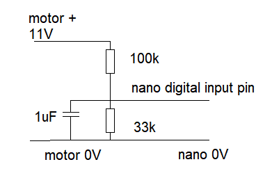
use a 3:1 divider - say 100k:33k with a capacitor - say 1uF and connect to the nano digital input.
ah, ok. How exactly would I do that? Sorry, I usually just use sensors. When I said non-interruptive, I just meant that I don't want it to lower how the motor preforms in any way.
Also, this is the battery I'm using if you were wondering. I also can't use the adafruit sensor I previously mentioned because It can't handle the mha and amps it uses.
I'm not sure I understand. An arduino with an IR sensor can easily handle 40 rounds/second. I don't see why measuring current is an advantage.
Ah, ok. Thank you! I'll try this out. This won't have any affect on the performance of the motor?
Also will these parts work?
I do have a question about your diagram though. I know that the resistors turn the voltage to about 3v and the capacitor is to get a steady flow of electricity, but if you put that 3v directly to the ground of the nano and the motor, won't that be connecting a positive and negative and short something out? I'd like to go into electrical engineering in my (distant) future and I would like to understand this sort of thing.
Describe where in the drawing you see this happening.
yes - except
https://www.amazon.com/EDGELEC-100pcs-Resistor-Resistance-Tolerance/dp/B07SG2TXWH
you need 100k ohm not 1 ohm.
the 3V goes to the nano digital input pin, not to ground.
Its connected to ground through the 33k resistor - so you get a current of 3V / 33000
= 0.0001 amp
thats not a short circuit.
Ah, ok. Thank you for taking the time to respond!!
This topic was automatically closed 180 days after the last reply. New replies are no longer allowed.