Hello,i am trying to connect a Fotek pl-05N proximity sensor to an Arduino uno interrupt pin.This sensors can be power supplied from 10-30 volt DC.I supply them from a battery that is connected to a charger so the voltage is about 14volt.The problem is that when the sensor is inactive I get 14 volts at the sensor signal output.When the sensor is triggered it drops down to 0volts.I made a voltage divider with a capacitor and a zener diode and the voltage dropped to 5volts when inactive and 0v when active.I use the capacitor to filter the signal because sometimes it get noise and gives me false triggers on rising.the max frequency I want is 250Hz.I measured the sensor output and I got 10k resistor.The problem is that the sensor seems to have very low current output and can't trigger my Arduino input.I think of using an Arduino external pullup resistor.Can anyone help me.I have attached a schematic of circuit and the output waveform on an emulator

I would try a simple voltage divider: 10K from +14V to the NPN output and 4.7K from the NPN output to ground.
The junction of the 10K and 4.7 K should vary between 4.5 and 0V, which will be safe for the Arduino and sensed as 1 or 0 by a digital input.
Would a simple diode, cathode to the sensor and anode to arduino, works?
Ciao, Ale.
Would a simple diode, cathode to the sensor and anode to arduino, works?
Probably, if there is also a pullup resistor to Vcc. The internal pullup might be enough, but I would use a lower value (say 10K) for noise resistance.
Hi,
Look here..
The sensor has an NPN open collector, if you have BLUE to gnd of 12V supply AND arduino gnd, BROWN to your 12V, then BLACK to arduino 5V via 1K0 resistor you should be getting 0 to 5V pulses at the arduino input.
You do have the gnd of the arduino connected to the gnd/neg of the 12V supply for the sensor?

Tom....
PS.What are you sensing with the proxy sensor?
TomGeorge:
The sensor has an NPN open collector, if you have BLUE to gnd of 12V supply AND arduino gnd, BROWN to your 12V, then BLACK to arduino 5V via 1K0 resistor you should be getting 0 to 5V pulses at the arduino input.
If you look at the datasheet (http://www.fotek.com.tw/pdf/etc_227.pdf), schematic on page 2, it seems that is NOT open collector, the NPN output transistor is connected to positive supply by a 4.7 Kohm resistor.
Ciao, Ale.
Hi,
And that is why I don't use or recommend FOTEK.
The whole idea of open collector is to enable different drive and output levels.
Tom... ![]()
TomGeorge:
Hi,
Look here..
AU Fotek PL-05N 5mm NPN Normal Open Proximity Sensor Switch DC10-30V New | eBayThe sensor has an NPN open collector, if you have BLUE to gnd of 12V supply AND arduino gnd, BROWN to your 12V, then BLACK to arduino 5V via 1K0 resistor you should be getting 0 to 5V pulses at the arduino input.
You do have the gnd of the arduino connected to the gnd/neg of the 12V supply for the sensor?
Tom....
PS.What are you sensing with the proxy sensor?
Thank's for your answer.I bought this sensor because it was described as NO NPN sensor.The 3 wire colors are
Brown-->Power Supply 10 to 30V DC
Blue-->Ground
Black-->Signal Out
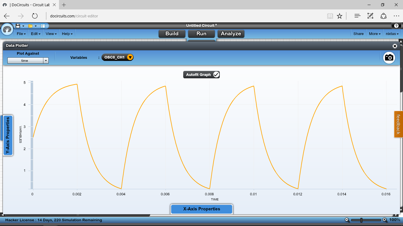
After testing I figured that the Black Cable(output) gives you the voltage you power supply the sensor.In my case the 12Volts as I installed a voltage regulator today when is not triggered and ground when it triggers.Also the internal resistance of the sensor as I measure it from output and ground is 10KOhm.I want to give more details about my project because I am really at the end of it(I believe)and I have problem with noise at my input.I have two sensors installed on my motorcycle one on front wheel and one on the rear and I am measuring the wheel speeds.I have tested my project on a breadboard and it works fine but when i install it on my motorcycle I get false input triggers.i use interrupts and the sensors cables especially the front one passes under my fuel tank were are the spark plugs.when the bike is turned on and I get a reading from the wheel sometimes it gives false triggers.i used a oscilloscope at the input of Arduino and I got something like the picture attached.i also attach the circuit I use.The power supply of my sensors and my Arduino is supplied from my motorcycle battery after a voltage regulator.


Any automobile/motorcycle electronics will be subjected to extreme noise and hazards like generator load dump, ignition spikes, etc.
You need to use shielded cable for all connections and have automotive electrical noise suppressors on the Arduino/sensor power supply lines.
jremington:
Any automobile/motorcycle electronics will be subjected to extreme noise and hazards like generator load dump, ignition spikes, etc.You need to use shielded cable for all connections and have automotive electrical noise suppressors on the Arduino/sensor power supply lines.
Every proximity sensor I have found so far,doesn't seem to have a shielded cable.Do you have one to suggest?
jremington:
Probably, if there is also a pullup resistor to Vcc. The internal pullup might be enough, but I would use a lower value (say 10K) for noise resistance.
I tested my sensor as you said on breadboard with a 1N4148 diode cathode facing sensor output and anode my Arduinos input and used a external 10K pullup resistor for Arduino.Seems to work.Do you think that this way I will stop all positive voltages even spikes and have only ground trigger my input?
Do you think that this way I will stop all positive voltages even spikes and have only ground trigger my input?
It will help, but will not affect spikes in the Arduino power line.
You can buy all types of shielded cable in many places.
jremington:
It will help, but will not affect spikes in the Arduino power line.You can buy all types of shielded cable in many places.
Sensors come with a mounted cable about 1 meter usually from what I have searched so far and can't be removed from sensor as it is an IP66 or IP67 for outdoor use.My power source is from my battery it is connected to an lm7812 which has 0.1uF capacitors on input and output and then is connected to my Arduino and my sensors.Do you think I need to add some filtering to my power and if yes can you suggest what.Thank's
Hi,
What could be causing your problem is the phyical detection area, not distance, of the end of the sensor compared to the physical distance between the teeth on the gear you are detecting.
Sensors designed for SPEED are specified as SPEED sensors, because of the different hall effect sensor arrangement in the end designed for geartooth detection, not proximity.
Check the direction, HORZ or VERT, of detection.
Also, what is the voltage hat you are supplying to the input of the 7812?
Do you have it bypassed as per the data spec for the 7812?
Can you please post a copy of your circuit, in CAD or a picture of a hand drawn circuit in jpg, png?
Thanks.. Tom... ![]()
TomGeorge:
Hi,What could be causing your problem is the phyical detection area, not distance, of the end of the sensor compared to the physical distance between the teeth on the gear you are detecting.
Sensors designed for SPEED are specified as SPEED sensors, because of the different hall effect sensor arrangement in the end designed for geartooth detection, not proximity.
Check the direction, HORZ or VERT, of detection.
Also, what is the voltage hat you are supplying to the input of the 7812?
Do you have it bypassed as per the data spec for the 7812?Can you please post a copy of your circuit, in CAD or a picture of a hand drawn circuit in jpg, png?
Thanks.. Tom...
I must tell you that when my motorcycle engine is not started and I only power my circuit and roll the motorcycle by pushing it the speeds are ok.the sensors are reading from 5 screws of the disk brakes on each wheel and I get very good signals.The problem occurs when I start the engine and roll the motorcycle.Then sometimes when the sensor triggers it gives some more pulses while rising or sometimes when falling

Hi,
If the battery supply is 12V, then your battery voltage will vary between 11V and 13.8V.
The 7812 needs at least 3V above 12V output to get a REGULATED 12V output.
So your input volts needs to be 15Vdc, the regulator is not able to give you a constant 12V.
Also the 7812 needs 10uF 16V capacitor between its output and gnd pins, the 0.1uF caps you have should be soldered as close as possible to the 7812.
Your best regulator here will be DCtoDC smps converter.
Tom... ![]()
TomGeorge:
Hi,
If the battery supply is 12V, then your battery voltage will vary between 11V and 13.8V.The 7812 needs at least 3V above 12V output to get a REGULATED 12V output.
So your input volts needs to be 15Vdc, the regulator is not able to give you a constant 12V.Also the 7812 needs 10uF 16V capacitor between its output and gnd pins, the 0.1uF caps you have should be soldered as close as possible to the 7812.
Your best regulator here will be DCtoDC smps converter.
Tom...
i will try to test with an external switching power supply the same one i used on my breadboard and had stable measures.if i get wrong measures when my bike is turned on then i guess all is caused from engine noise spikes.is it correct?